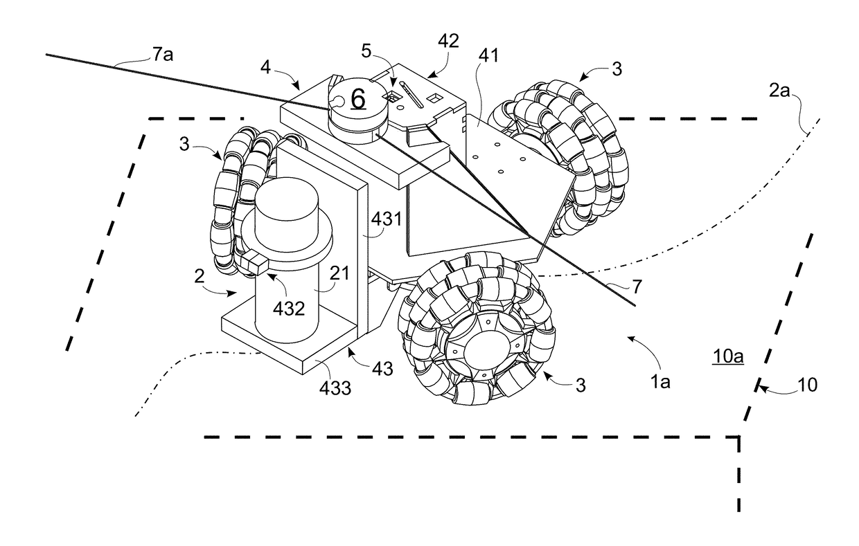
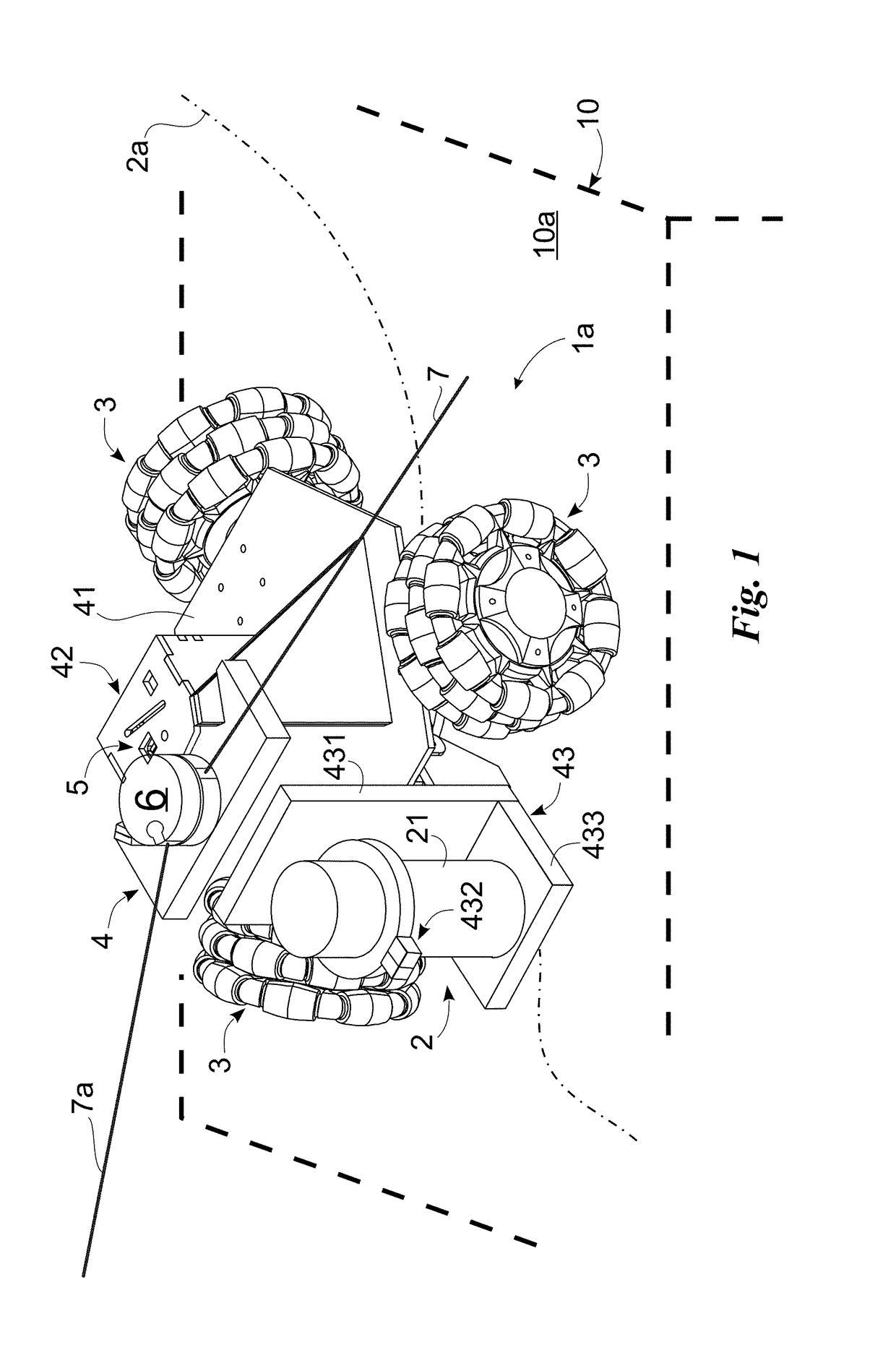
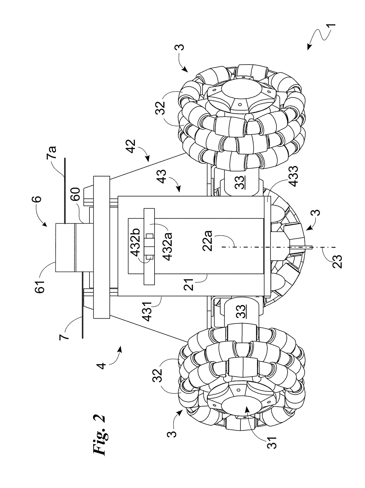
Tool system and method of operation of said tool system

a tool system and tool technology, applied in the field of tool system and method of operation of said tool system, can solve the problems of high danger risk, operator may seriously injure himself/herself, and high dexterity and experience, and achieve the effect of reducing purchase, maintenance and running costs, reducing size, and facilitating and safe operation of any cutting profil

Active Publication Date: 2018-11-22
SPRINGA SRL
View PDF0 Cites 1 Cited by
  • Summary
  • Abstract
  • Description
  • Claims
  • Application Information

AI Technical Summary

Benefits of technology

[0026]Within the sphere of said technical purpose one important aim of the invention is to obtain a tool system having reduced purchase, maintenance and running costs. Another important aim of the invention is to make a machine system of reduced size.
[0027]A further purpose of the invention is to develop a tool system and method of operation of the same which can easily and safely perform any cutting profile on an object of any size.

Problems solved by technology

A first disadvantage is that to make non-rectilinear shapes or profiles, the movement of the tool or workpiece is performed manually by the operator who must thus have high dexterity and experience.
Another drawback is the high risk of danger and, therefore, the fact that the operator may seriously injure him / herself.
This problem is further increased by the fact that the safety guard is often removed to improve the visibility of the cut or blade.
Another drawback is that the operator, to perform different types of machining, is forced to both buy several machines, increasing production costs and to move the object between the different machines, increasing processing times.
One important drawback is the limited size of an object worked with these machines since, having to be inserted in the machining chamber, they cannot have large dimensions.
Another drawback is that CNC machines have a highly complex construction and, therefore, a high purchase and maintenance cost.
Another drawback is the high energy consumption of such machines, which, together with the aforesaid high purchase and maintenance costs, make the pieces produced this way particularly expensive.
Another drawback is that the CNC machines require the operator to have an advanced knowledge of the machine and of the programming language and are thus complex to program and use.
The aforementioned technique however has at least one further significant drawback.
There is however no reference with respect to the reference system defined by the part being machined and therefore it is not possible to operate the tool in relation to the support surface.
The lack of information relative to the surface of the part being machined thus makes it impossible to automatically determine the position of the device on the work surface.

Method used


Image

  • Tool system and method of operation of said tool system
  • Tool system and method of operation of said tool system
  • Tool system and method of operation of said tool system

Examples


Embodiment Construction

[0047]Herein, the measures, values, shapes and geometric references (such as perpendicularity and parallelism), when used with words like “about” or other similar terms such as “approximately” or “substantially”, are to be understood as except for measurement errors or inaccuracies due to production and / or manufacturing errors and, above all, except for a slight divergence from the value, measure, shape or geometric reference which it is associated with. For example, said terms, if associated with a value, preferably indicate a divergence of not more than 10% of said value.

[0048]In addition, where used terms such as “first”, “second”, “upper”, “lower”, “main” and “secondary” do not necessarily refer to an order, a priority relationship or relative position, but may simply be used to more clearly distinguish different components from each other.

[0049]The measurements and data presented herein are considered, unless otherwise indicated, as performed in International Standard Atmospher...


PUM

PropertyMeasurementUnit
heightaaaaaaaaaa
heightaaaaaaaaaa
heightaaaaaaaaaa

Abstract

Provided is a tool system for including a machine tool configured for machining by the removal of material an object defining a machining surface.

Description

FIELD OF THE INVENTION[0001]The present invention relates to a tool system and method of operation of said tool system of the type comprising a machine tool suitable for machining by the removal of material an object defining a machining surface, wherein the machine tool comprises a tool, driving means suitable to be placed directly in contact with the machining surface and to move the machine tool and, thus, the removal tool, with respect to the object while the removal tool removes material from the object, and a control unit for controlling the driving means.[0002]In particular, the device which the present invention relates to is a system in which the movement of a machine tool during machining is directed by a computer which controls its movements and functions according to a clearly-defined work programme.DESCRIPTION OF THE PRIOR ART[0003]As known, machine tools divide depending on the type of machining or tool into lathes, drills, sanders, milling machines, and usually includ...

Claims


Application Information

Patent Timeline
Patent Type & Authority Applications(United States)
IPC IPC(8): B23Q9/00B23Q17/24G05B19/409
CPCB23Q9/0007B23Q17/2414G05B19/409B60B19/125B23Q9/00G01B3/11G01B5/004G05D1/0227G05D2201/0216B23Q17/22Y10T409/306384Y10T29/5176
Inventor TRIFONI, ALESSANDROCEVOLI, DAVIDEFRANGI, LORENZO
Owner SPRINGA SRL
Why Eureka
Try Eureka