Bi-directional beacon information system

Active Publication Date: 2018-11-22
CHASE ARNOLD +1
View PDF12 Cites 60 Cited by
  • Summary
  • Abstract
  • Description
  • Claims
  • Application Information

AI Technical Summary

Benefits of technology

[0019]Although the present system is primarily designed to work with autonomous vehicles, much of it is also of benefit for human-driven vehicles as well, acting as a back-up to the human operator to improve safety. As the balance between autonomous vehicles and driven vehicles on the roads tips in favor of autonomous vehicles, at some point the “driven” vehicles will increasingly need to be equipped with BBIS beacons to safely operate in the “new” autonomous environ

Problems solved by technology

Until guidance systems on-board autonomous vehicles match or exceed the perception and analytical decision-making ability of human drivers, there will be numerous ongoing daily situations which will frustrate the ability of a full autonomous vehicle to properly and dynamically respond to, or react to, its surroundings.
Moreover, until autonomous vehicles can safely rely upon its operational systems and sensors to safely and efficiently operate a vehicle and eliminate essentially all risks, the public will continue to be hesitant to put full faith in true autonomous operation of such vehicles.
Drivers would receive notifications and alerts of dangerous situations, such as a potential red-light violations; icy roads ahead; or an oncoming car, out of sight beyond a curve, swerving into their lane to avoid an object on the road.” However, this initiative and other similar projects, as of yet, do not allow autonomous vehicles to fully address the challenges facing them for true autonomous operation and proper safe and efficient driverless operation.
As a result, no system has been developed that can fully accomplish the goals of the USDOT Program.
While the existing level of “on-board” sensors, cameras, devices, and interfaces can alter an autonomous vehicle's driving characteristics to a limited degree (e.g., by braking for unexpected obstacles and/or other vehicles

Method used


Image

  • Bi-directional beacon information system
  • Bi-directional beacon information system
  • Bi-directional beacon information system

Examples


Embodiment Construction

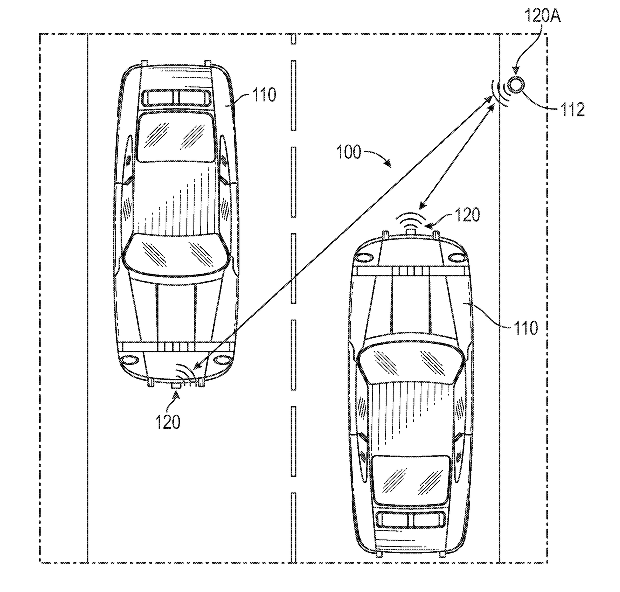
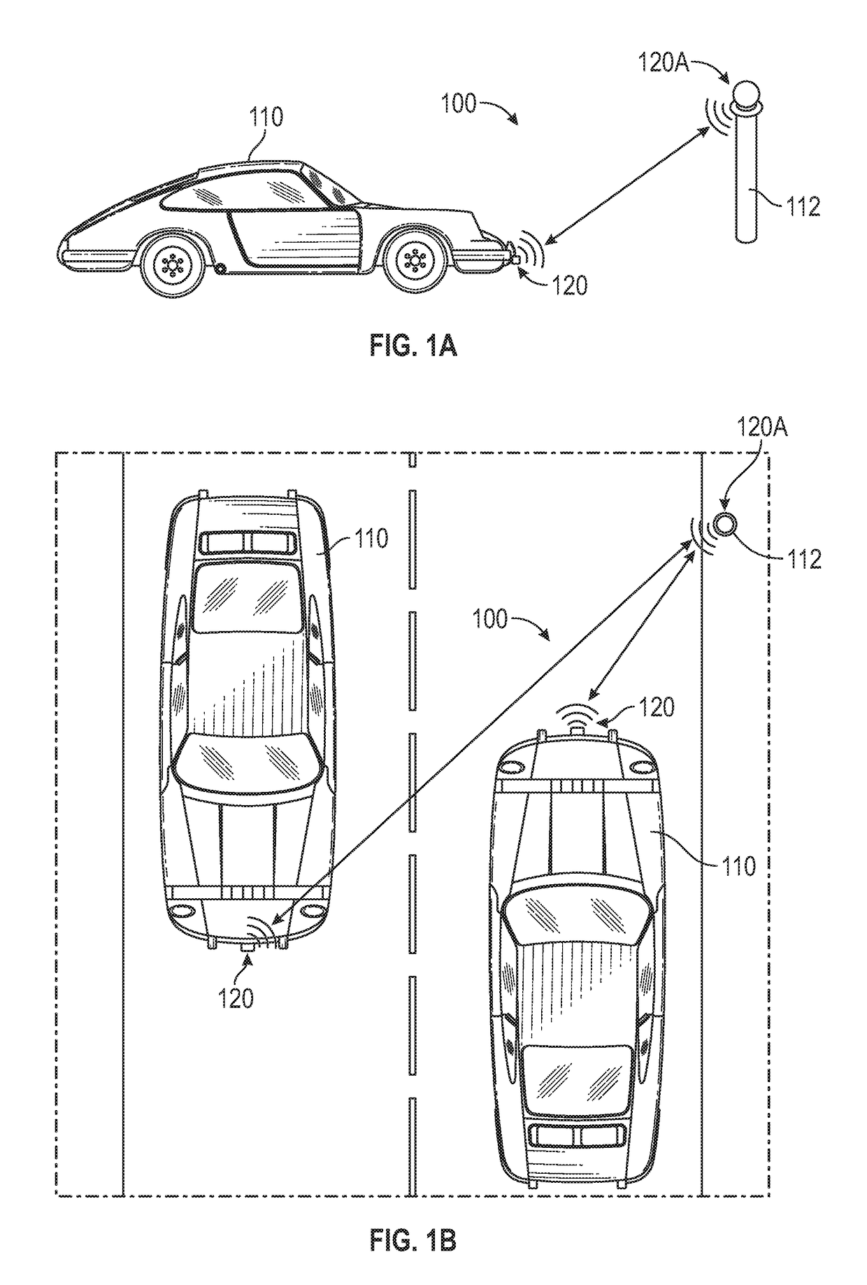
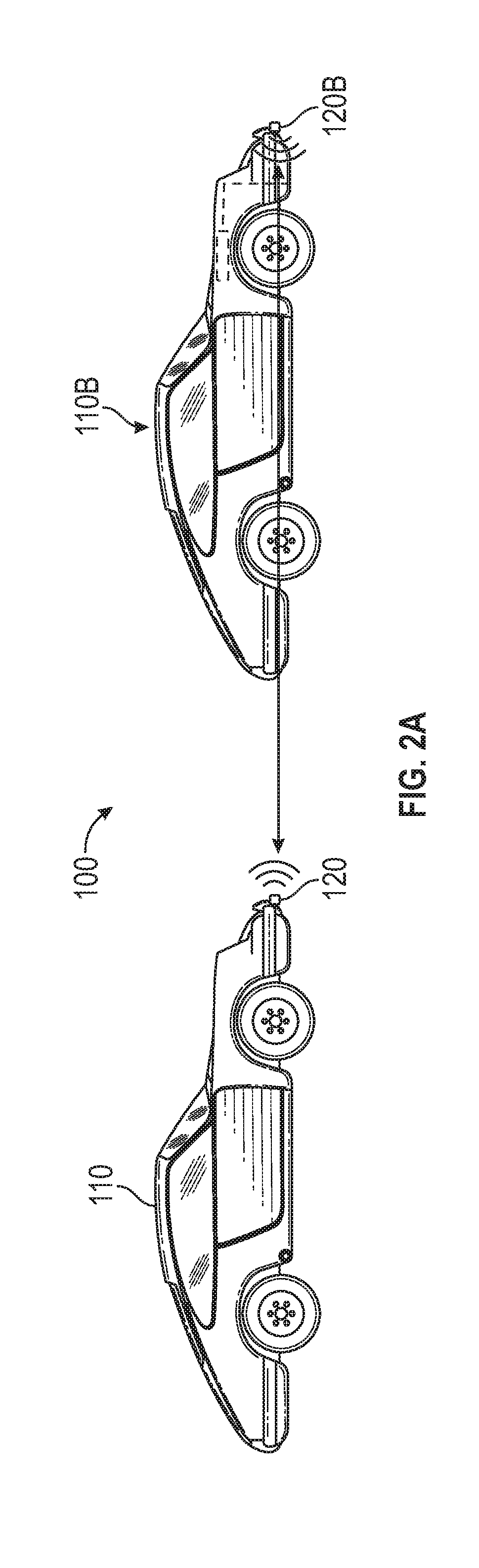
[0025]Exemplary embodiments of a BBIS in accordance with the present invention are illustrated in FIGS. 1 and 2, and generally designated by reference numeral 100. As shown, an autonomous vehicle 110 is equipped with a BBIS beacon, general designated by reference numeral 120 and which preferably includes a transmitter 122 and a receiver 124, or alternatively a singular transceiver, for bi-directional communication. As illustrated in FIG. 4, the BBIS beacon system is in operational communication with a CAN Bus 130 disposed on the vehicle 110, which communicates with or includes a processor 132 handling autonomous operation of the vehicle 110 in combination with the vehicle's operating systems, GPS system, differential GPS system, and the like, generally represented as reference numeral 134.

[0026]Preferably, the BBIS beacon 120, which includes the transmitter 122 and receiver 124, is located on the vehicle 110 in a position where it can pick up transmissions from other beacons 120 wit...


PUM


Abstract

An autonomous vehicle is equipped with a beacon, preferably including a transmitter and receiver, or a transceiver, for bi-directional communication, which is programmed to interact with other beacons for the exchange of contextual travel information to assist in autonomous operation of the vehicle. Beacons may be stationary and positioned along a roadway such that a signal transmitted by such a stationary beacon can be received by a passing beacon-equipped vehicle, the operation of which can be adjusted depending on instructions received from the stationary beacon. The vehicle can also transmit information to the stationary beacon, which information can be used to assess traffic conditions to thereafter adjust information and alerts sent to other beacon-equipped vehicles. Beacons located within multiple vehicles may also interact to share information that may be used by individual vehicles to adjust or maintain the autonomous operation of the vehicle.

Description

CROSS-REFERENCE TO RELATED APPLICATIONS[0001]This application claims the benefit under 35 U.S.C. § 119(e) of U.S. Provisional Application No. 62 / 509,335, filed May 22, 2017, which is incorporated herein by reference in its entirety.TECHNICAL FIELD OF THE INVENTION[0002]The present invention generally relates to augmenting and enhancing the remote operation of autonomous vehicles, and more particularly relates to a system for assisting in the safe and efficient operation of autonomous vehicles on public roadways, more particularly in dealing with unknown, unexpected or unpredicted traffic situations or driving conditions on the roadway.BACKGROUND OF THE INVENTION[0003]Many companies are developing autonomous vehicles for commercial and personal use on existing roadways for a variety of applications, including but not limited to personal taxi services, delivery services, and the like. In accordance with the present invention, an autonomous vehicle is a vehicle capable of operating wit...

Claims


Application Information

Patent Timeline
IPC IPC(8): G05D1/02G08G1/01G08G1/0967G08G1/0968G05D1/00
CPCG05D1/028G08G1/0112G08G1/0116G08G1/0133G08G1/0141G08G1/096708G08G1/096822G05D1/0234G05D1/0022G05D2201/0213G08G1/0145G08G1/096758G08G1/096783G08G1/096791
Inventor CHASE, ARNOLDCHASE, WILLIAM
Owner CHASE ARNOLD
Why Eureka
Try Eureka