
Driving circuit and liquid crystal display device

Active Publication Date: 2018-11-22
SHENZHEN CHINA STAR OPTOELECTRONICS SEMICON DISPLAY TECH CO LTD
View PDF0 Cites 1 Cited by
  • Summary
  • Abstract
  • Description
  • Claims
  • Application Information

AI Technical Summary

Benefits of technology

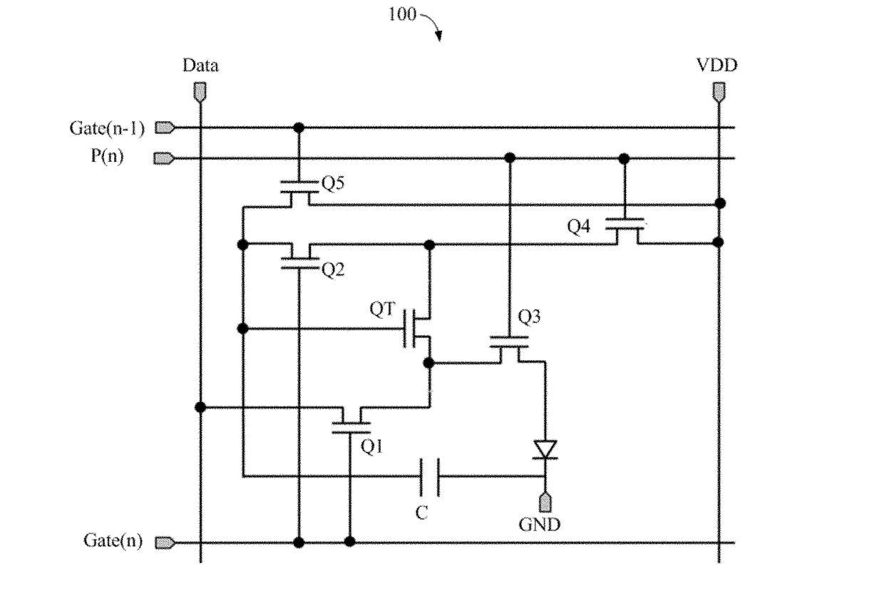
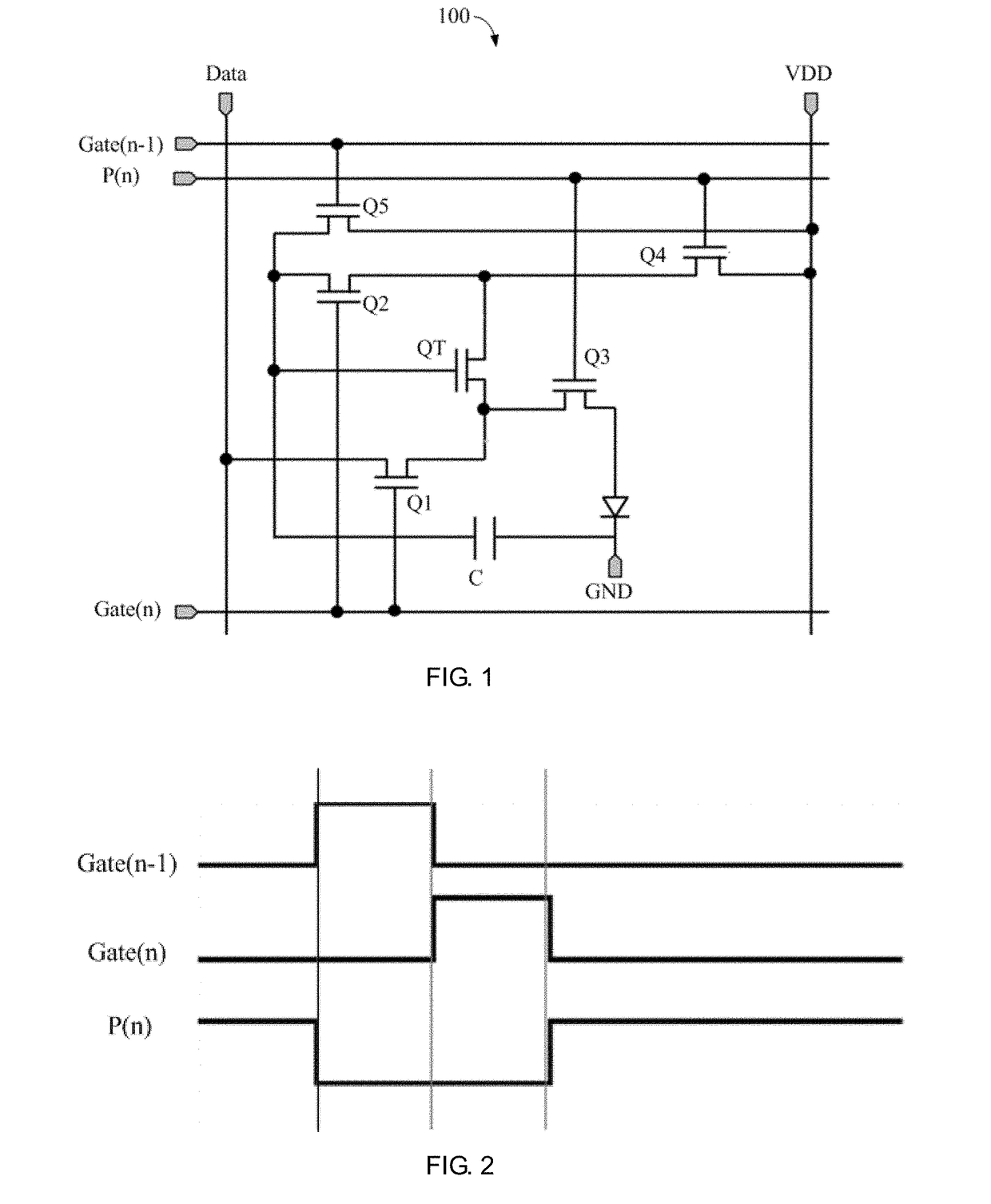
The present invention is about a driving circuit for a liquid crystal display device that uses an organic light emitting diode (OLED) to produce light. The circuit includes multiple electrical switches and a capacitor. The first switch controls a driving scan line, receives a data signal, and connects to the second and third switches. The second switch controls a compensation scan line. The fourth switch connects to the anode of the OLED while the capacitor connects to the cathode of the OLED and ground. The driving circuit constantly turns on, and the compensation scan line is turned on when the driving circuit is at a high voltage level. The third and fourth switches are turned on and the first and second switches are turned off, which keeps the current of the driving switch constant and ensures that the brightness of the OLED remains unchanged, resulting in a constant display.

Problems solved by technology

The change in the threshold voltage of the driving thin film transistor will inevitably cause a change in the output current of the driving thin film transistor.
The change in the output current of the driving thin film transistor will inevitably cause a change in the brightness of the organic light emitting diode, thus influencing the normal display of the organic light emitting diode.

Method used


Image

  • Driving circuit and liquid crystal display device
  • Driving circuit and liquid crystal display device
  • Driving circuit and liquid crystal display device

Examples


Embodiment Construction

[0023]Embodiments of the present invention are described in detail with the technical matters, structural features, achieved objects, and effects with reference to the accompanying drawings as follows. It is clear that the described embodiments are part of embodiments of the present invention, but not all embodiments. Based on the embodiments of the present invention, all other embodiments to those of ordinary skill in the premise of no creative efforts obtained, should be considered within the scope of protection of the present invention.

[0024]Besides, the following descriptions for the respective embodiments are specific embodiments capable of being implemented for illustrations of the present invention with referring to appended figures. For example, the terms of up, down, front, rear, left, right, interior, exterior, side, etcetera are merely directions of referring to appended figures. Therefore, the wordings of directions are employed for explaining and understanding the prese...


PUM


Abstract

Disclosed is a driving circuit, comprising first to fourth electrical switches, a driving electrical switch and capacitor. The control end and second end of the first switch are coupled to a driving scan line and second end of the driving switch. The control end, first end and second end of the driving switch are coupled to the capacitor, a second end of the second switch and a first end of the fourth switch. A control end of the second switch is coupled to the driving scan line. The control end of the third switch respectively is coupled to a first compensation scan line and receives a direct current voltage. The control end and second end of the fourth switch are coupled to a compensation scan line and an anode of an organic light emitting diode. The capacitor is coupled to a cathode of the organic light emitting diode and grounded.

Description

CROSS REFERENCE[0001]This application claims the priority of Chinese Patent Application No. 201710208517.3, entitled “Driving circuit and liquid crystal display device”, filed on Mar. 31, 2017, the disclosure of which is incorporated herein by reference in its entirety.FIELD OF THE INVENTION[0002]The present invention relates to a display technology field, and more particularly to a driving circuit and a liquid crystal display device.BACKGROUND OF THE INVENTION[0003]A traditional organic light emitting diode driving circuit comprises two thin film transistors and a storage capacitor. One thin film transistor is a switching thin film transistor and the other thin film transistor is a driving thin film transistor. After driving for a long period of time, the threshold voltage of the driving thin film transistor drifts due to the long-term voltage application. The change in the threshold voltage of the driving thin film transistor will inevitably cause a change in the output current of...

Claims


Application Information

Patent Timeline
IPC IPC(8): G09G3/34G09G3/36
CPCG09G3/3406G09G3/3648G09G2320/0233G09G3/3225G09G3/3233G09G2300/0819G09G2300/0842G09G2300/0861
Inventor SHI, LONGQIANG
Owner SHENZHEN CHINA STAR OPTOELECTRONICS SEMICON DISPLAY TECH CO LTD
Learn More