Data reception apparatus, data transmission system, data reception method, and data transmission method
a data reception and data transmission technology, applied in the field of data transmission systems, data reception methods, data reception methods, etc., can solve problems such as lowering network quality, affecting audio quality, and affecting video quality
- Summary
- Abstract
- Description
- Claims
- Application Information
AI Technical Summary
Benefits of technology
Problems solved by technology
Method used
Image
Examples
first embodiment
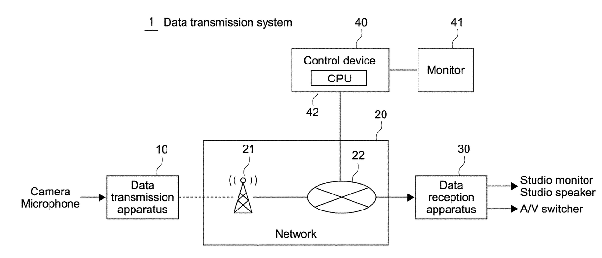
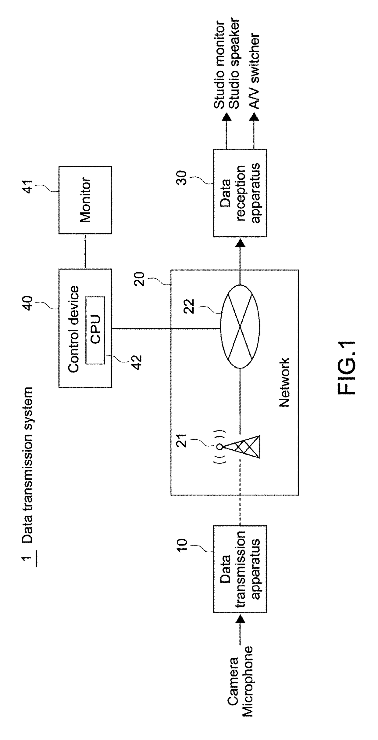
[0058]FIG. 1 is a diagram showing a configuration of a data transmission system of a first embodiment according to the present technology.
[0059]This data transmission system 1 is a system that transmits video and audio data (streams) obtained by a camera and a microphone. This data transmission system 1 is constituted of a data transmission apparatus 10, a network 20, a data reception apparatus 30, and a control device 40.
[0060]For example, the network 20 is a WWAN (Wireless Wide Area Network) 21 such as an LTE (Long Term Evolution), a WAN 22 such as the Internet, or a combination of a plurality of such networks 20 and is a communication channel whose communication traffic changes every minute.
[0061]The data transmission apparatus 10 may be in the form of an adaptor detachably mounted on the camera, for example, or may be integrally incorporated in the camera. In this embodiment, the data transmission apparatus 10 in the form of the adaptor is assumed.
[0062]The data reception appara...
modified example 1
[0149]The data transmission system according to the present technology can be utilized not only in the case of talking between the spot and the studio but also in a case of recording the spot's video and audio in a recording device such as a server while a staff of a broadcast station is monitoring them.
[0150]FIG. 10 is a diagram showing a configuration of a recording system of the broadcast station.
[0151]This recording system 90 mainly includes the data reception apparatus 30, a recording monitor 91, a recording speaker 92, and a recording device 93.
[0152]In the data reception apparatus 30, the spot's video and audio generated using a first error correction-allowed time are output to the recording device 93 by the first A / V output interface 34.
[0153]Further, in the data reception apparatus 30, the spot's video and audio generated using a second error correction-allowed time are output to the recording monitor 91 and the recording speaker 92 by the second A / V output interface 35. Th...
modified example 2
[0157]In the first embodiment, the user can manually set the first error correction-allowed time using the management GUI. However, the first error correction-allowed time may be adaptively controlled in accordance with the error rate, the transmission delay, and the like during communication.
[0158]To be specific, as shown in FIG. 9, the CPU 42 (second controller) of the control device 40 monitors at least either one of an error rate and a transmission delay during communication in accordance with the application program for control and sends an instruction for changing the first error correction-allowed time to the reception apparatus 30 in real time in accordance with a detected result. The CPU 31 of the reception apparatus 30 changes the first error correction-allowed time in real time in accordance with this instruction from the control device 40. Here, the first error correction-allowed time may be set to be variable in two or more steps.
[0159]Further, along with the change in ...
PUM
 Abstract
Description
Claims
Application Information
 - R&D
- Intellectual Property
- Life Sciences
- Materials
- Tech Scout
- Unparalleled Data Quality
- Higher Quality Content
- 60% Fewer Hallucinations
Browse by: Latest US Patents, China's latest patents, Technical Efficacy Thesaurus, Application Domain, Technology Topic, Popular Technical Reports.
© 2025 PatSnap. All rights reserved.Legal|Privacy policy|Modern Slavery Act Transparency Statement|Sitemap|About US| Contact US: help@patsnap.com


