Power steering device

a technology of power steering and steering assist mechanism, which is applied in the direction of electrical steering, fluid steering, vehicle components, etc., can solve the problem that the first steering assist mechanism cannot generate the large assist force required, and achieve the effect of preventing an excessive load, increasing power consumption, and reducing power consumption

Active Publication Date: 2018-11-29
TOYOTA JIDOSHA KK
View PDF11 Cites 10 Cited by
  • Summary
  • Abstract
  • Description
  • Claims
  • Application Information

AI Technical Summary

Benefits of technology

[0022]The temperature of the driving circuit including the semiconductor device configured to control the amount of current supply to the first electric motor increases as an average drive current of the first electric motor increases. According to the embodiment, the present invention device sets a smaller threshold indication amount as the temperature of the semiconductor device increases (in other words, the power consumption increases), and sets a larger threshold indication amount as the temperature of the semiconductor device decreases (in other words, the power consumption decreases). Thus, the present invention device can prevent an excessive load from being applied to the first electric motor.

Problems solved by technology

Therefore, the first steering assist mechanism cannot generate a large assist force required in a low-speed travelling, steering without driving, and the like.

Method used


Image

  • Power steering device
  • Power steering device
  • Power steering device

Examples


first embodiment

[0042](Configuration)

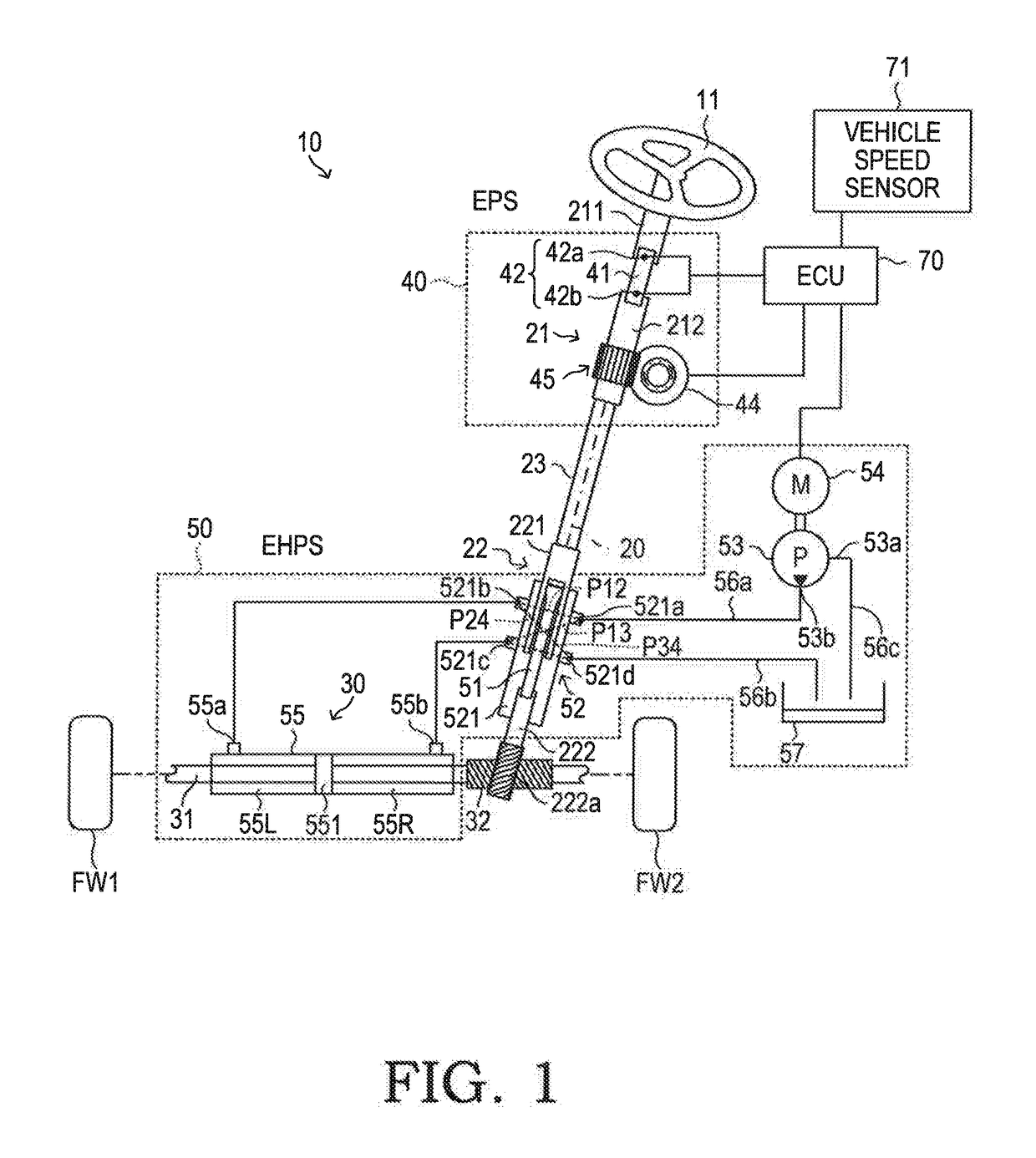
[0043]A power steering device (hereinafter also referred to as “first device”) 10 according to a first embodiment of the present invention is applied to a vehicle. As illustrated in FIG. 1, the first device 10 includes a steering wheel 11, a steering shaft 20, and a rack shaft 30. The steering shaft 20 includes a first steering shaft 21, a second steering shaft 22, and an intermediate shaft 23.

[0044]The steering wheel 11 is coaxially coupled to one end of the first steering shaft 21 for integral rotation. When a driver carries out an operation (turn operation) on the steering wheel 11, the first steering shaft 21 rotates about an axis. This rotation is transmitted to the second steering shaft 22 via the intermediate shaft 23, and the second steering shaft 22 thus also rotates about an axis. The first steering shaft 21 includes a first shaft 211 and a second shaft 212. A first torsion bar 41 is provided between the first shaft 211 and the second shaft 212.

[0045]O...

second embodiment

[0111]Next, a description is given of a power steering device (hereinafter also referred to as “second device”) according to a second embodiment of the present invention. The second device is different from the first device 10 in that not the magnitude |T| of the steering torque but indicators correlating with a speed (hereinafter also referred to as “steering speed”) of the operation on the steering wheel 11 are used as the second-electric-motor drive start condition. In the following, a description is mainly given of the point that indicators correlating with the steering speed are used as the second-electric-motor drive start condition.

[0112]In a case where the second-electric-motor drive start condition is the threshold steering torque Tth as in the first device 10, when the magnitude |T| of the steering torque reaches the threshold steering torque Tth, the second-electric-motor drive start condition is satisfied independently of a load state of the electric assist motor 44 of t...

third embodiment

[0146]Next, a description is given of a power steering device (hereinafter also referred to as “third device”) according to a third embodiment of the present invention. The third device is different from the first device 10 and the second device in that the third device has a function of avoiding (preventing) entrance into an overload state of the electric assist motor 44. In the following, a description is mainly given of the function of avoiding the entrance into the overload state of the electric assist motor 44.

[0147]In order to improve the fuel efficiency of the vehicle, it is effective to delay the start of the assist by the EHPS 50 as much as possible as stated in the description of the second embodiment (second device). Meanwhile, when the start of the assist by the EHPS 50 is delayed, the electric assist motor 44 may enter the overload state. However, the electric assist motor 44 is required to be used within a range of a rated power. Thus, the third device is configured to...


PUM


Abstract

The power steering device is configured to: apply a required assist force only from a first electric motor until a predetermined period elapses, which is a period from a time point at which a driver starts steering to a time point at which a second-electric-motor drive start condition, which is a condition for starting drive of a second electric motor, is satisfied; when the predetermined period has elapsed, apply the required assist force from the first electric motor and a hydraulic actuator; and adjust an assist force by the first electric motor so that the assist force by the first electric motor is a value obtained by subtracting an assist force by the hydraulic actuator from the required assist force. As a result, the device can be downsized, and a sufficient required assist force can be generated from an initial stage of the steering.

Description

BACKGROUND OF THE INVENTION1. Field of the Invention[0001]The present invention relates to a power steering device configured to apply a steering assist force (hereinafter sometimes simply referred to as “assist force” or “assist torque”) to a steering mechanism.2. Description of the Related Art[0002]Hitherto, there has been known a power steering device (hereinafter referred to as “conventional device”) capable of applying to a steering mechanism an assist force for assisting an operation (hereinafter also referred to as “steering”) on a steering wheel from both an electric assist motor and a hydraulic actuator. This hydraulic actuator is operated by acting of hydraulic fluid supplied from an electric hydraulic pump.[0003]When a required assist force is smaller than a predetermined value, the conventional device does not operate the electric hydraulic pump, and generates the assist force only by the electric assist motor. Further, when the required assist force is larger than the p...

Claims


Application Information

Patent Timeline
Patent Type & Authority Applications(United States)
IPC IPC(8): B62D5/04B62D5/06B62D5/12
CPCB62D5/0463B62D5/0409B62D5/064B62D5/12B62D5/065B62D6/02
Inventor UEYAMA, MASAO
Owner TOYOTA JIDOSHA KK
Why Eureka
Try Eureka