Battery fuel gauge circuit

a fuel gauge and battery technology, applied in secondary cells, electrical equipment, cell structural combinations, etc., can solve the problems of increasing the error in the initial soc, ocv cannot be measured with sufficient precision, etc., and achieve the effect of reducing the noise

Active Publication Date: 2018-11-29
ROHM CO LTD
View PDF5 Cites 5 Cited by
  • Summary
  • Abstract
  • Description
  • Claims
  • Application Information

AI Technical Summary

Benefits of technology

[0018]Also, the first A / D converter may sample the voltage of the battery for every predetermined sampling period. Also, when the power supply for the device is turned on for the first time, the logic circuit may acquire an average value of the multiple voltage values of the battery sampled immediately before the first-time turning-on of the power supply. By calculating the average value, this arrangement is capable of reducing the effects of noise or the like.

Problems solved by technology

Accordingly, the OCV cannot be measured with sufficient precision when the battery is charged or discharged.
With this control operation, if a long time elapses from a time point at which the OCV is measured in a state in which the battery is mounted up to a time point at which the user turns on the power supply for the first time, this leads to an increase in error in the initial SOC because the battery discharges during this period of time.

Method used


Image

  • Battery fuel gauge circuit
  • Battery fuel gauge circuit
  • Battery fuel gauge circuit

Examples


modification 1

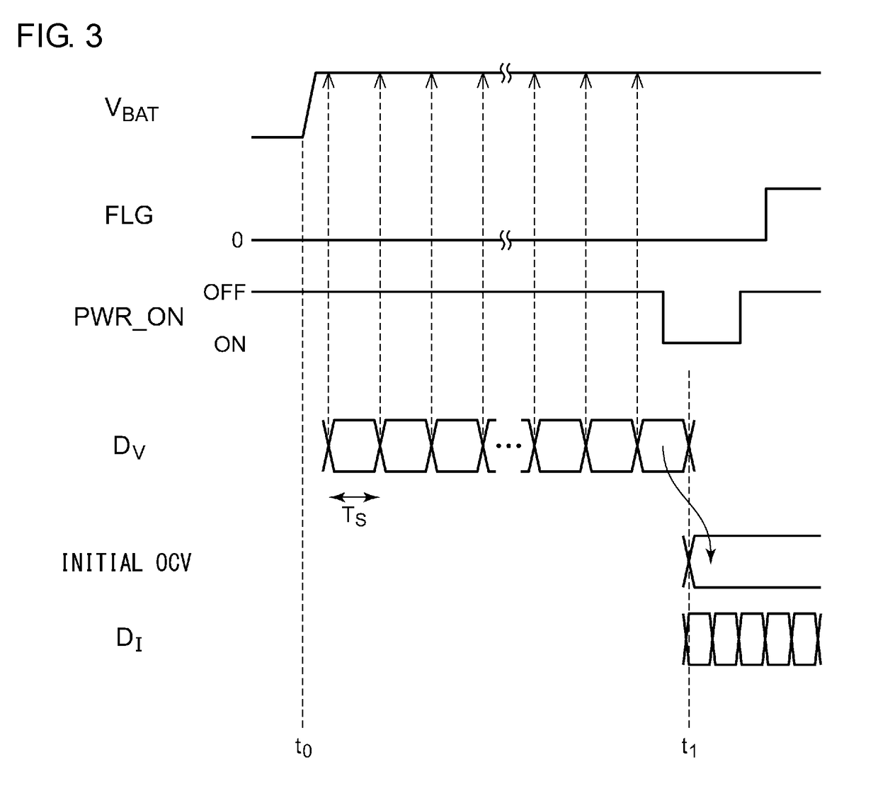
[0073]Description has been made in the embodiment regarding an arrangement as shown in FIG. 3 in which the single voltage detection value DV immediately before the turning-on of the power supply button (time point t1) is used as the initial OCV. However, the present invention is not restricted to such an arrangement. FIG. 5 is a diagram for explaining the measurement of the initial OCV according to a modification 1. For example, an average of multiple voltage detection values DV measured immediately before the time point t1 may be used as the initial OCV. As the average processing, simple average calculation or weighted average calculation may be employed. Alternatively, moving average calculation may be employed. Also, the voltage detection values DV to be used for the average calculation may be measured in a time-based series. Also, such data to be used for the average calculation may be extracted for every N (N≥2) data items.

[0074]FIG. 6 is a flowchart for explaining the operatio...

modification 2

[0075]FIG. 7 is a diagram for explaining the measurement of the initial OCV according to a modification 2. In a case in which the battery 102 remains in the relaxed state immediately after the time point t1, the voltage detection value DV measured immediately after the time point t1 may be used as the initial OCV.

[0076]FIG. 8 is a flowchart for explaining the operation of the electronic device 100 according to the modification 2. When judgment has been made that the turning-on of the power supply thus detected is the first-time turning-on (YES in S106), the battery voltage VBAT is sampled once more (S103). The voltage detection value DV thus acquired in the last sampling (S103) is held as the initial OCV (S108).

modification 3

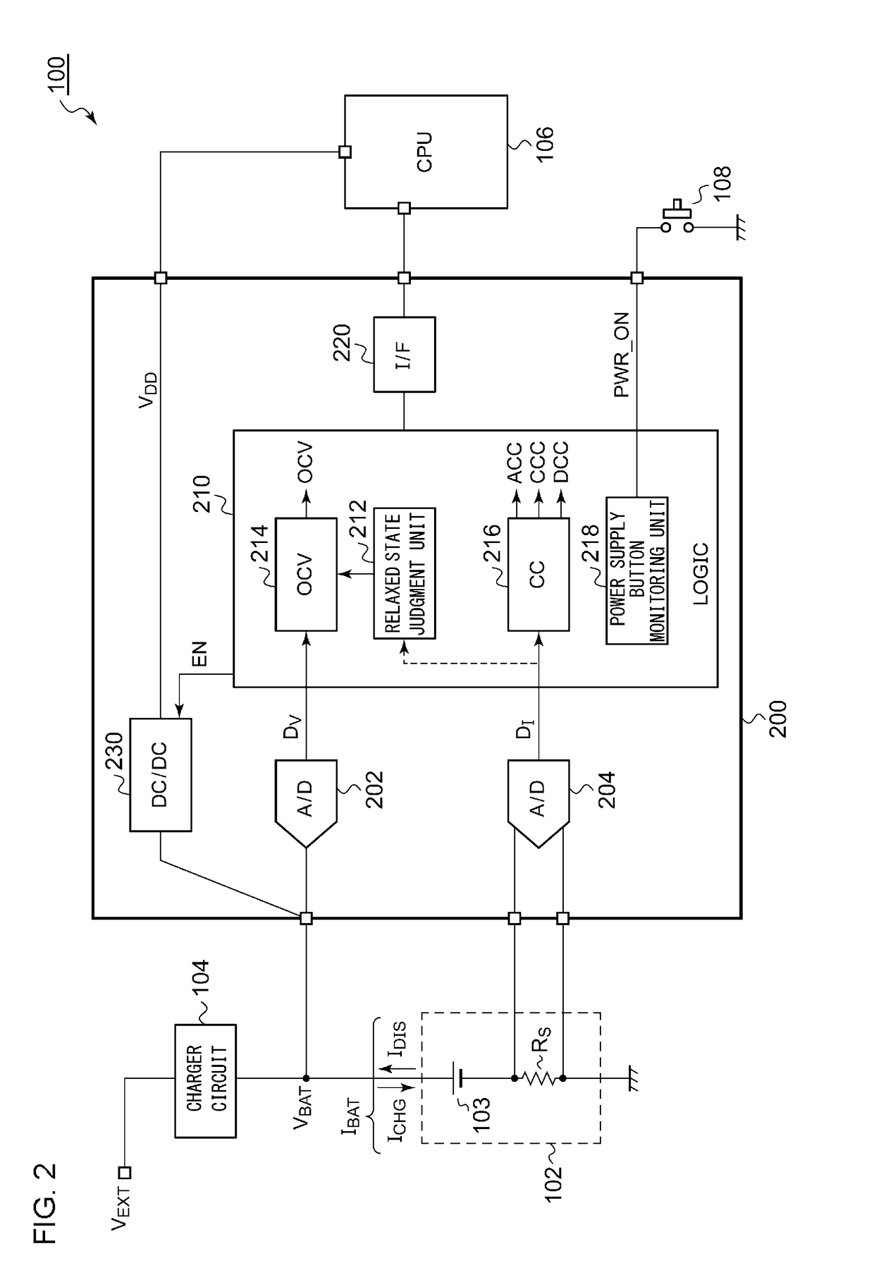
[0077]Description has been made in the embodiment regarding an arrangement in which a part of the estimation of the SOC and the calculation is executed by the CPU 106 configured as an external component of the battery fuel gauge circuit 200. However, the present invention is not restricted to such an arrangement. Also, a processor (calculation core) may be integrated on the battery fuel gauge circuit 200 in order to integrate a part of the functions of the CPU 106.


PUM

PropertyMeasurementUnit
voltageaaaaaaaaaa
voltagesaaaaaaaaaa
currentaaaaaaaaaa

Abstract

A battery fuel gauge circuit is coupled to a rechargeable battery. A first A/D converter samples a voltage VBAT of the battery. A logic circuit receives the output of the first A/D converter. The logic circuit acquires the output of the first A/D converter when an electronic device mounting the battery fuel gauge circuit is turned on for the first time.

Description

BACKGROUND OF THE INVENTIONCROSS REFERENCE TO RELATED APPLICATIONS[0001]The present application claims priority under 35 U.S.C. § 119 to Japanese Patent Application No. 2017-105482, filed on May 29, 2017 and Application No. 2018-085778, filed on Apr. 26, 2018, the entire content of which are incorporated herein by reference.1. Field of the Invention[0002]The present invention relates to a battery management system.2. Description of the Related Art[0003]Various kinds of battery-driven electronic devices such as cellular phone terminals, digital still cameras, tablet terminals, portable music players, portable game machines, and laptop computers include a built-in chargeable battery (secondary battery). Electronic circuits such as a CPU (Central Processing Unit) adapted to system control operation and signal processing, a liquid crystal panel, a wireless communication module, and other kinds of analog circuits and digital circuits, each operate receiving power supplied from the batter...

Claims


Application Information

Patent Timeline
Patent Type & Authority Applications(United States)
IPC IPC(8): H01M10/42
CPCH01M10/4285H01M10/425H01M2010/4271Y02E60/10
Inventor SHIMADA, KAZUAKI
Owner ROHM CO LTD
Why Eureka
Try Eureka