Power Converter

Active Publication Date: 2018-11-29
BAYERISCHE MOTOREN WERKE AG
View PDF1 Cites 1 Cited by
  • Summary
  • Abstract
  • Description
  • Claims
  • Application Information

AI Technical Summary

Benefits of technology

[0025]A plurality of the switching elements of the first parallel circuit arrangement or the second parallel circuit arrangement can be arranged on a chip and/or on a substrate. Particularly good thermal coupling is achieved as a result. For example, the substrate can be a ceramic substrate and the transistors can be arranged on the substrate by way of so-called chip-on-board technology (chip on the substrate). However, it is also possible for a plurality of the switching elements of the first parallel circuit arrangement or the second parallel circuit arrangement to be arranged in a common housing without a lower housing. Good heat transmission and thus more uniform current d

Problems solved by technology

The application of such inverters in an electrically driven vehicle places high demands on the electronic components.
Power losses arise during operation of the power transistors.
On the one hand, power losses arise during the time for which the power transistor is switched on.
There are also switching losses, which arise when the transistor

Method used


Image

  • Power Converter
  • Power Converter
  • Power Converter

Examples


Example

DETAILED DESCRIPTION OF THE DRAWINGS

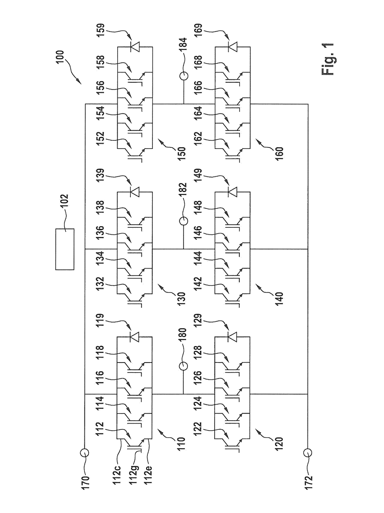
[0036]FIG. 1 shows a schematic diagram of a current converter 100 according to an embodiment of the invention. A rechargeable battery is connected to terminals 170 and 172, for example via a link circuit store and a DC / DC converter, or a DC link circuit. A phase of the three-phase current, for example in each case a winding of an electric machine for driving a vehicle, can be connected to the taps 180, 182, 184. The current converter 100 functions as an inverter or a controlled or regulated rectifier.

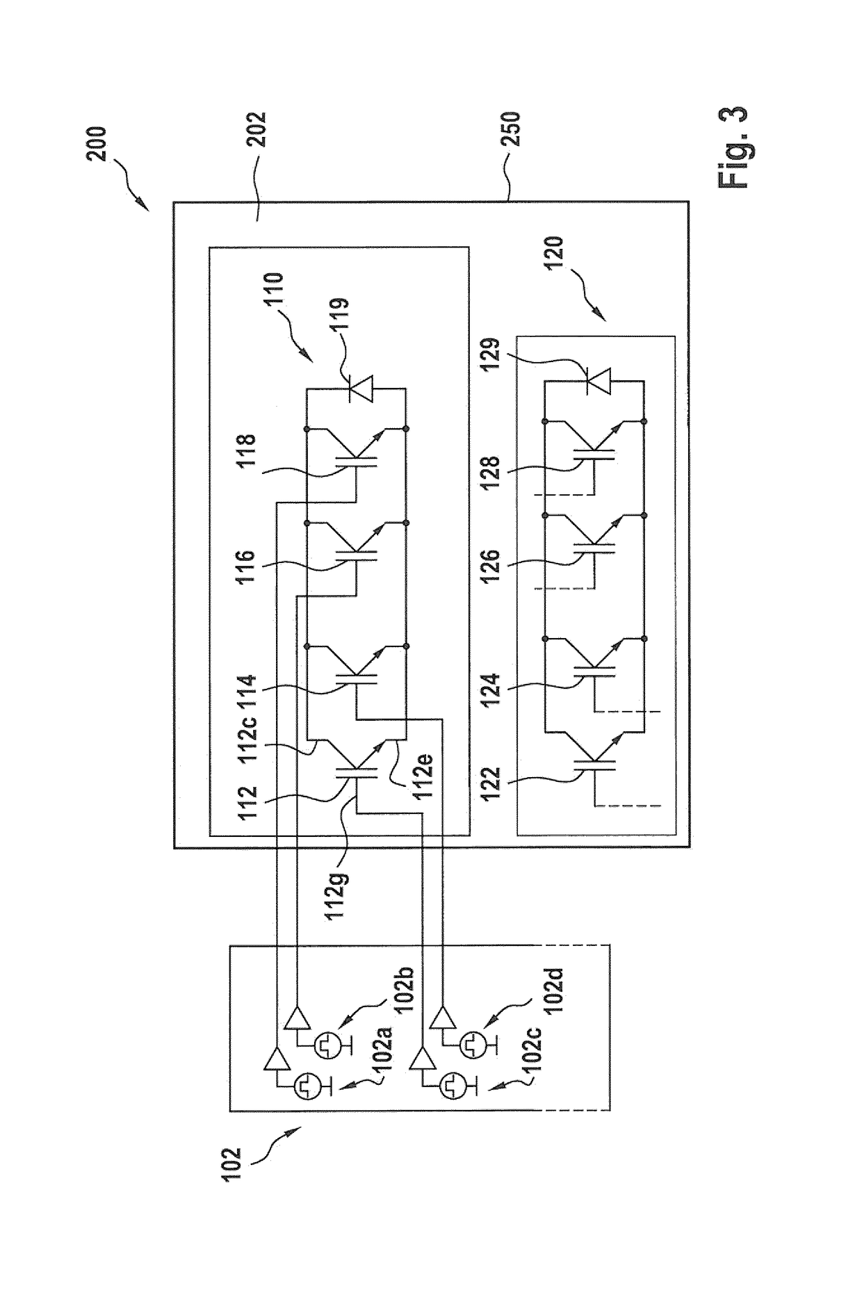
[0037]The current converter 100 includes one or more half-bridges and, in the example shown in the figures, three half-bridges. The first half-bridge is formed by the series circuit of a first parallel circuit arrangement 110 having a plurality of transistors 112, 114, 116, 118 and a second parallel circuit arrangement 120 having a plurality of parallel-connected transistors 122, 124, 126, 128. A freewheeling diode 119, 129 is connected in parallel wi...


PUM


Abstract

A power converter including a bridge circuit is provided. The power converter is designed to convert a direct current of a current source into an alternating current and/or an alternating current into a direct current. The bridge circuit includes a first parallel circuit assembly, which is coupled to a higher potential of the current source and which has a plurality of switching elements connected in parallel, a second parallel circuit assembly, which is coupled to a lower potential of the current source and which has a plurality of switching elements connected in parallel, and a plurality of taps, which are each coupled to the first and second parallel circuit assemblies. Each switching element of the first and the second parallel circuit assemblies has two conducting connections and a control connection, which controls the flow of current from one conducting connection to the other conducting connection. The power converter also includes a control device, which is designed in such a way that, when the power converter is operated at partial load, at least one switching element of a parallel circuit assembly is controlled in such a way that said switching element is not switched on during at least one cycle. The switching elements of a parallel circuit assembly are thermally coupled to one another.

Description

CROSS REFERENCE TO RELATED APPLICATIONS[0001]This application is a continuation of PCT International Application No. PCT / EP2017 / 051703, filed Jan. 27, 2017, which claims priority under 35 U.S.C. § 119 from German Patent Application No. 10 2016 201 504.4, filed Feb. 1, 2016, the entire disclosures of which are herein expressly incorporated by reference.BACKGROUND AND SUMMARY OF THE INVENTION[0002]The present invention relates to an improved current converter for an electrically driven vehicle, in particular an improved inverter.[0003]Inverters are used in electrically driven vehicles to convert the direct current from a rechargeable battery to a polyphase alternating current for driving an electric machine. The principles of electric drives are known to those skilled in the art and do not have to be described further here for the sake of conciseness.[0004]Such current converters typically use three half-bridges, wherein two transistors are connected in series in each half-bridge. The...

Claims


Application Information

Patent Timeline
IPC IPC(8): H02M7/219H02M7/23H02M7/5387H02M1/088
CPCH02M7/219H02M7/23H02M7/5387H02M1/088H02M7/493
Inventor HAMERSKI, ROMANRIEFLE, CARSTEN
Owner BAYERISCHE MOTOREN WERKE AG
Why Eureka
Try Eureka