Thermal conductivity detector

a detector and thermal conductivity technology, applied in the direction of material thermal conductivity, material thermal analysis, instruments, etc., can solve the problems of temporary temperature imbalance, limited detection limit of thermal conductivity detector, and different affecting of detector components, so as to improve the detection limit

Active Publication Date: 2015-08-06
SIEMENS AG
View PDF8 Cites 5 Cited by
  • Summary
  • Abstract
  • Description
  • Claims
  • Application Information

AI Technical Summary

Benefits of technology

[0009]Since the portions of the thermal conduction block that carry the detector components are thermally connected only via the central portion, the thermal path length or distance is the same between all detector components such that thermal crosstalk coming from any detector component affects each of the other detector components in the same way and can thus be easily compensated if (for example) one of the other detector components measures a reference gas.
[0011]In an alternative embodiment, the thermal conduction block is formed in several parts comprising the peripheral portions that arranged around and in contact with the central portion. All usual types of connection, such as welding, brazing, bonding, screwing, plugging, etc., are possible as long as they provide a good thermal coupling of the peripheral portions to the central portion. In one embodiment, the peripheral portions may be separated from each other by spacers with low thermal conductivity to provide equal spacing between all neighboring peripheral portions and to improve the overall stability of the multi-part thermal conduction block.
[0013]In one embodiment, to further improve the evenness of the heat distribution, the peripheral portions each may comprise a lower part and an upper part that, when mounted together, form a cavity between them as the receptacle for the detector component. The receptacles may be filled with a thermal paste.

Problems solved by technology

The detection limit of the thermal conductivity detector may be limited by thermal crosstalk between the detector components.
Having different wall temperatures creates a temporary temperature imbalance within the thermal conduction block that affects the detector components differently.
The thermal symmetry of the known thermal conductivity detectors is not good enough to compensate for this effect.

Method used


Image

  • Thermal conductivity detector
  • Thermal conductivity detector
  • Thermal conductivity detector

Examples


Embodiment Construction

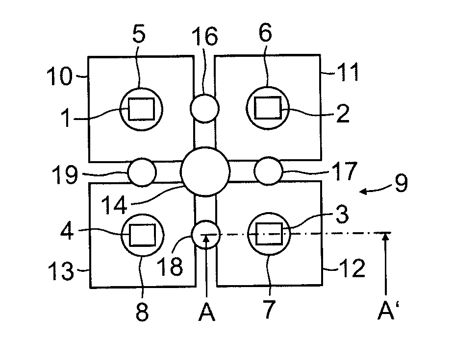
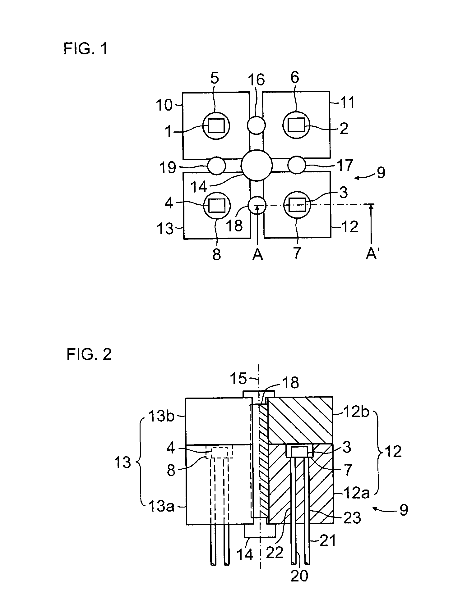
[0020]The thermal conductivity detector shown in FIGS. 1 and 2 comprises four detector components 1, 2, 3, 4, which are accommodated in receptacles 5, 6, 7, 8 formed on the top side of a thermal conduction block 9. The thermal conduction block includes several parts and comprises four peripheral portions 10, 11, 12, 13 arranged around and in contact with a central portion 14. All portions 10-14 are made of a highly heat-conductive material such as brass, copper or aluminum.

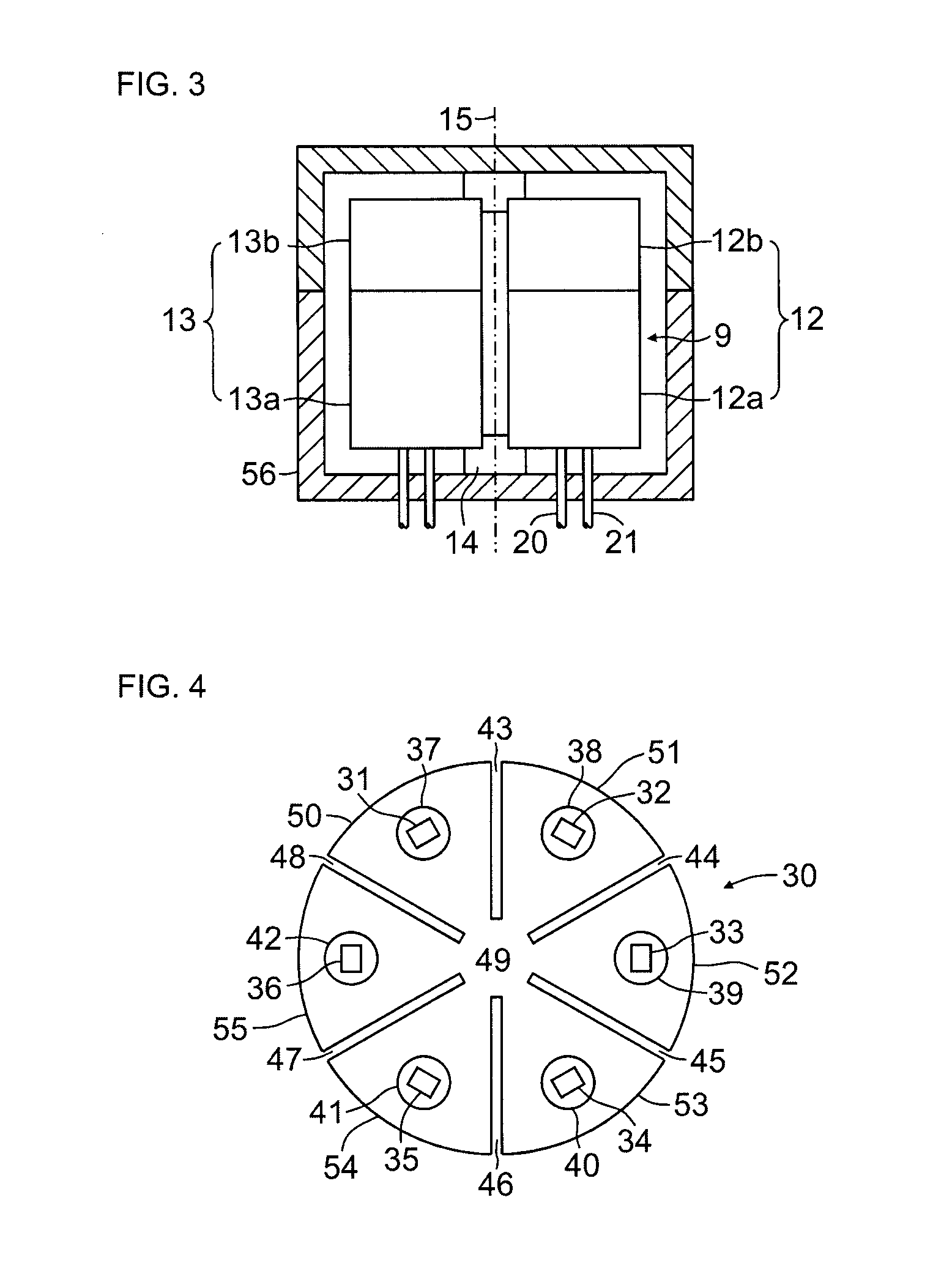
[0021]In the shown example, the peripheral portions 10-13 each have a rectangular cross section and the central portion 14 has a circular cross section. Generally, the portions of the thermal conduction block 9 can be of any cross section as long as the peripheral portions 10-13 are equal and the central portion 14 is n-fold, here n=°4, rotationally symmetrical. Accordingly, the receptacles 5-8 and the detector components 1-4 contained therein are situated in a circle around a center axis 15 of the thermal conduct...


PUM

PropertyMeasurementUnit
thermal conductivityaaaaaaaaaa
diameteraaaaaaaaaa
electrical resistanceaaaaaaaaaa

Abstract

A thermal conductivity detector includes at least four detector components that are arranged in receptacles of a thermal conduction block in a circle around a center axis of the thermal conduction block. The thermal conduction block comprises a central portion along the axis, the cross-axial dimensions of the central portion being less than the diameter of the circle. There are at least four equal peripheral portions that are connected solely to the central portion and are separated from each other, each of the peripheral portions carrying one of the detector components.

Description

BACKGROUND OF THE INVENTION[0001]1. Field of the Invention[0002]The present application generally relates to a thermal conductivity detector comprising at least four detector components arranged in receptacles of a thermal conduction block in a circle around a center axis of the thermal conduction block.[0003]2. Related Art[0004]Thermal conductivity detectors, such as those disclosed in U.S. Pat. No. 2,512,857, U.S. Pat. No. 3,474,660 or DE 103 18 450 B3, are used to detect certain liquid or gaseous substances (fluids) on the basis of their characteristic thermal conductivity, particularly in gas chromatography. To that end, the substances to be detected are successively guided past an electrically heated filament disposed in a channel, after their chromatographic separation. Depending on the thermal conductivity of the substance flowing past, more or less heat is diverted from the heating filament to the channel wall, and the heating filament is correspondingly cooled to a greater ...

Claims


Application Information

Patent Timeline
Patent Type & Authority Applications(United States)
IPC IPC(8): G01N27/18
CPCG01N30/66G01N27/18
Inventor GELLERT, UDO
Owner SIEMENS AG
Why Eureka
Try Eureka