Sensor system and method for its manufacture

a technology of a sensor and a manufacturing method, applied in the field of sensor systems, can solve the problems of not being suitable for automatic assembly on a printed circuit board, both sides of the printed circuit board are constantly exposed to the humidity to be measured, and additional production costs, etc., to achieve the effect of low manufacturing expenditure, good measuring accuracy and great robustness

Inactive Publication Date: 2008-10-21
E E ELEKTRONIK GES
View PDF14 Cites 6 Cited by
  • Summary
  • Abstract
  • Description
  • Claims
  • Application Information

AI Technical Summary

Benefits of technology

[0006]An example embodiment of the present invention may provide a sensor system which may be producible with low manufacturing expenditure, and which may exhibit great robustness, as well as good measuring accuracy. An example embodiment of the present invention may provide a cost-effective and reliable method for manufacturing a sensor system of this kind.
[0009]In an example embodiment of the present invention, provided between the thin-film sensor and the printed circuit board may be a mounting adhesive which, on one hand, may simplify the mounting operation and may increase the operational reliability of the method, and on the other hand, also may ensure good thermal coupling of the thin-film sensor to the printed circuit board. In this connection, it may be provided that the mounting adhesive exhibits high thermal conductivity, e.g., greater than 0.3 W / (m·K). The mounting adhesive may have thermal conductivity greater than, e.g., 0.5 W / (m·K).

Problems solved by technology

This type of construction may have the disadvantage that, during operation of the sensor system, both sides of the printed circuit board are constantly exposed to the humidity to be measured.
Moreover, additional production costs may result from the provision of the opening in the printed circuit board.
Such sensors may have the disadvantage that they are not, or are just barely, suitable for automatic assembly on a printed circuit board.

Method used


Image

  • Sensor system and method for its manufacture
  • Sensor system and method for its manufacture
  • Sensor system and method for its manufacture

Examples


Embodiment Construction

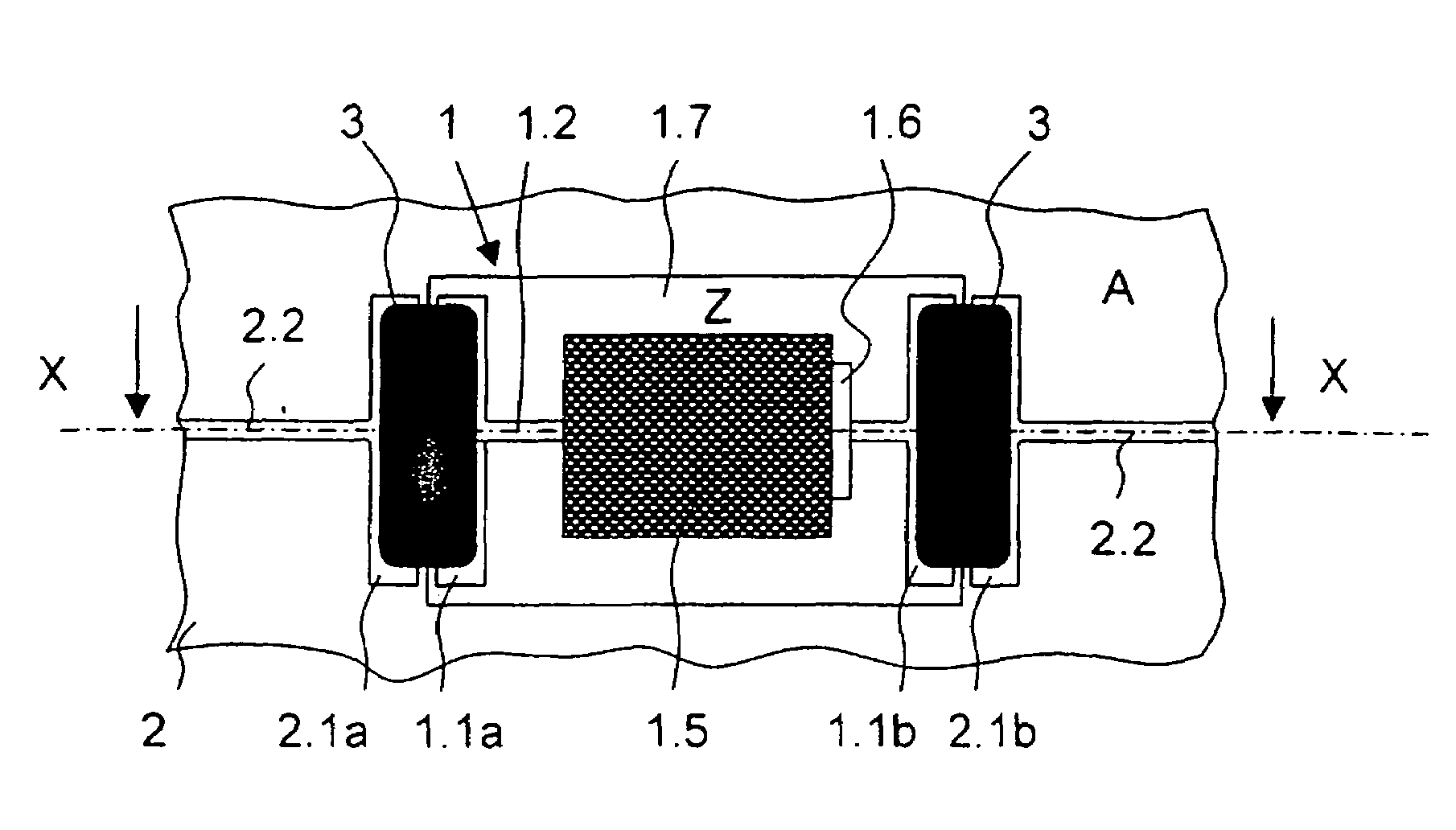
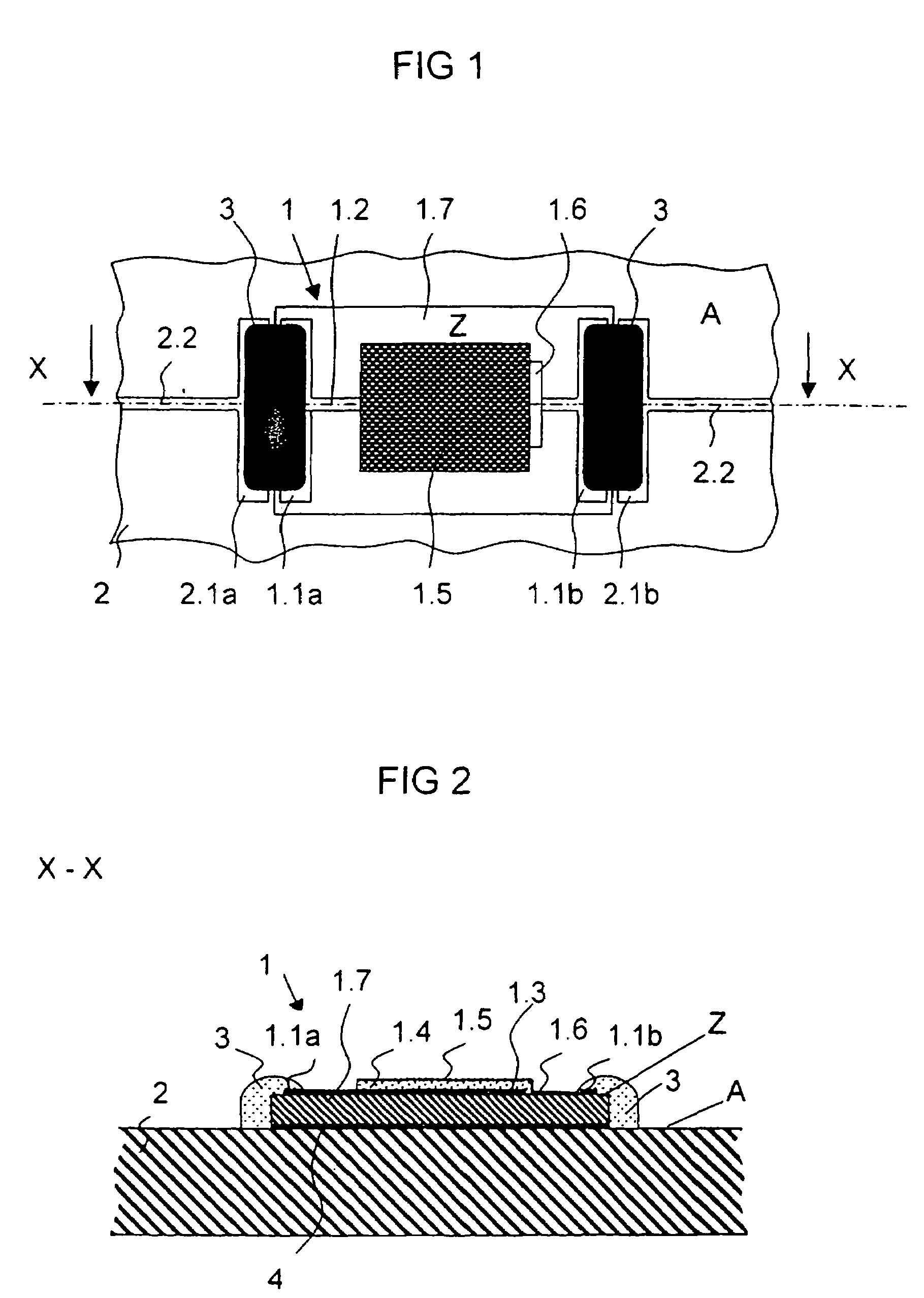
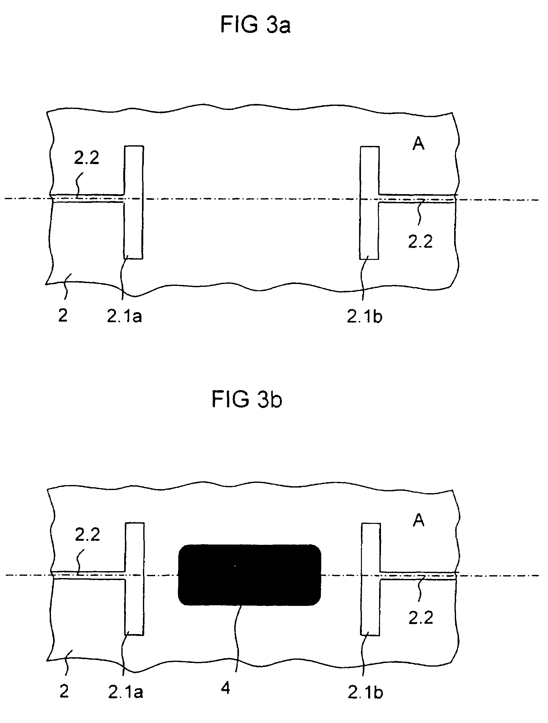
[0023]FIG. 1 is a top view of a sensor system according to an example embodiment of the present invention. The sensor system includes a thin-film sensor 1 and a printed circuit board 2, of which only a segment is illustrated.

[0024]Thin-film sensor 1 is used for measuring the relative air humidity, and is based on a capacitive functional principle. Thin-film sensor 1 includes a substrate 1.7, on whose surface Z a base electrode 1.3 (see FIG. 2), made of gold in the example illustrated, is applied. In the exemplary embodiment illustrated, substrate 1.7 is made of glass. Base electrode 1.3 is electrically connected via a conductor track 1.2 to a contacting area 1.1a. Both conductor track 1.2 and contacting area 1.1a are located on surface Z of substrate 1.7. A moisture-sensitive or humidity-sensitive polymer 1.4 is applied over base electrode 1.3 in a sensitive region of thin-film sensor 1. Applied on this moisture-sensitive polymer 1.4 is a porous moisture electrode 1.5 which is in el...


PUM

PropertyMeasurementUnit
thermal conductivityaaaaaaaaaa
areasaaaaaaaaaa
areaaaaaaaaaaa

Abstract

A sensor system includes a thin-film sensor provided with at least one contact area on the surface thereof, and a printed circuit board provided with at least one contact pad on the surface thereof. The thin-film sensor is arranged in relation to the surface of the printed circuit board such that the surface of the thin-film sensor opposes the surface of the printed circuit board. In order to transmit sensor currents from the thin-film sensor to the printed circuit board, a conductive glue adheres to both the contact area of the thin-film sensor and to the contact pad on the surface of the printed circuit board.

Description

FIELD OF THE INVENTION[0001]The present invention relates to a sensor system, e.g., for determining the relative humidity in air, and to a method for manufacturing such a sensor system.BACKGROUND INFORMATION[0002]Such sensor systems are often used for determining the relative humidity, for instance, in automotive air conditioners, in household appliances or in copier machines, and are consequently used in great quantities. As a cost-effective type of construction for the sensors used therein, so-called thin-film sensors are often used, whose functioning method is based, for example, on a capacitive measuring principle. The thin-film sensors are usually produced in planar fashion, i.e., all active films or layers as well as the contacting areas of the thin-film sensors are accommodated on one surface of the thin-film sensors. Generally, no coatings are then located on the back side of such thin-film sensors.[0003]To manufacture a functional sensor system in as automated a manner as p...

Claims


Application Information

Patent Timeline
Patent Type & Authority Patents(United States)
IPC IPC(8): G01R27/08G01R27/26G01N27/22
CPCG01N27/223G01N27/22
Inventor LINDORFER, GERALD
Owner E E ELEKTRONIK GES
Why Eureka
Try Eureka