Method and device for determining a measure of brake system usage during operation of a vehicle

a technology of brake system and measurement method, which is applied in the direction of vehicle sub-unit features, external condition input parameters, transportation and packaging, etc., to achieve the effect of higher acceleration threshold

Active Publication Date: 2018-12-06
SCANIA CV AB
View PDF2 Cites 2 Cited by
  • Summary
  • Abstract
  • Description
  • Claims
  • Application Information

AI Technical Summary

Benefits of technology

[0012]As was mentioned above, it is important for overall economy that vehicles are driven in an economical way by drivers, since fuel consumption is greatly affected by driver ability to utilize the energy that is stored in the vehicle when set in motion. It is generally desirable for fuel consumption to be as low as possible, since the larger the amount of energy consumed the more fuel will be required to propel the vehicle by means of the engine.
[0015]The present invention makes it possible to assess how a driver operates the vehicle for at least some situations and in a way which largely eliminates any effect of cargo or surroundings upon the assessment. This is achieved by determining the impact on the propulsion of the vehicle when the driver applies vehicle brakes.
[0018]A magnitude of the difference in acceleration that the applied brake force gives rise to can be determined, and the measure can be determined on the basis of this magnitude. This has the advantage that e.g. a more favourable measure, from an economical, fuel consumption, point of view, can be obtained, for lower influences on vehicle acceleration in comparison to higher influences. The measure can indicate various levels of economical driving, wherein a particular level can be arranged to depend on the magnitude of the influence on the vehicle acceleration caused by said request for brake force.
[0019]According to one embodiment, the magnitude of the difference in acceleration that said applied brake force gives rise to can be compared with an acceleration threshold, and it can be determined that driving is more economical when said magnitude of the difference in acceleration is below the acceleration threshold than when said magnitude of the difference in acceleration exceeds said acceleration threshold. A difference in acceleration that said applied brake force gives rise to being below said acceleration threshold can be considered as an economical way of driving said vehicle, while a higher difference in acceleration can be considered as excessive use of vehicle brakes that should be avoided.
[0020]The acceleration threshold can be arranged to differ in dependence of the inclination on the surface on which said vehicle is travelling. For example, the acceleration threshold can be higher when the vehicle is going downhill than when going uphill. The inclination in itself will decelerate the vehicle when going uphill, and accelerate the vehicle when going downhill, and the use of differing thresholds has the advantage that the thresholds can be adapted to allow a suitable overall vehicle acceleration for each driving situation.
[0022]Instead of comparing the difference in acceleration caused by the applied brake force with a threshold, the resulting vehicle acceleration can instead be compared with an acceleration threshold. That is, the resulting overall vehicle acceleration is used to represent influence on the vehicle acceleration caused by said request for brake force, and form basis of the measure. This has similar advantages to the above. Driving can be considered more economical when the magnitude of the vehicle acceleration is below the acceleration threshold than when the magnitude of the vehicle acceleration exceeds the acceleration threshold.

Problems solved by technology

Apart from the procurement cost of a vehicle, the main expense items for routine operation are pay for the driver, repair and maintenance costs and fuel for propulsion.

Method used


Image

  • Method and device for determining a measure of brake system usage during operation of a vehicle
  • Method and device for determining a measure of brake system usage during operation of a vehicle
  • Method and device for determining a measure of brake system usage during operation of a vehicle

Examples


Embodiment Construction

[0032]In the following description and claims the term acceleration is used. Acceleration can be positive, i.e. speed increasing or negative, i.e. speed reducing, in relation to a direction of motion. Hence the term acceleration is used in the following to denote also situations where the vehicle is decelerating, in which case the acceleration is negative. Further, the acceleration may be of various magnitudes, a higher magnitude resulting in harder acceleration, be it positive (speed increasing) or negative (decelerating).

[0033]Embodiments of the invention will be exemplified in the following in relation to a hybrid vehicle, but are also equally applicable to other vehicles, e.g. electric vehicles, and conventional vehicles such as vehicles being powered only by means of combustion engines.

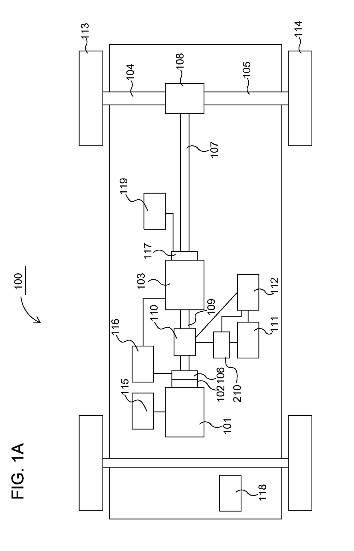
[0034]FIG. 1A schematically illustrates a general layout of a powertrain in a hybrid vehicle 100 according to embodiments of the invention. There exist various types of hybrid vehicles and the ve...


PUM


Abstract

A method, system and computer program product are provided for determining a measure of brake system usage during operation of a vehicle, the vehicle comprising a power source for generating a motive force for propulsion of the vehicle in a first direction of travel, and driver controllable means for requesting a brake force that acts against a movement of the vehicle in the first direction of travel. When a driver of the vehicle requests a brake force, the method comprises determining an influence on the vehicle acceleration caused by the request for brake force; and determining, based on the determined influence, a measure of brake system usage of the vehicle, the measure indicating a level of economical driving, wherein a particular level is arranged to depend on the magnitude of the influence on the vehicle acceleration caused by the request for brake force.

Description

CROSS-REFERENCE TO RELATED APPLICATION(S)[0001]This application is a National Stage Application (filed under 35 § U.S.C. 371) of PCT / SE2016 / 051181, filed Nov. 29, 2016 of the same title, which, in turn claims priority to Swedish Application No. 1551597-6 filed Dec. 4, 2015 of the same title; the contents of each of which are hereby incorporated by reference.FIELD OF THE INVENTION[0002]The present invention relates to a method, system and computer program product for determining a measure of brake system usage during operation of a vehicle, and in particular for determining a measure of applied brake force from a fuel consumption point of view. The invention also relates to a vehicle comprising such a system and / or a computer program product.BACKGROUND TO THE INVENTION[0003]Vehicles in general, and at least to some extent heavy vehicles in particular, are in focus of ongoing research and development relating to, inter alia, fuel efficiency and reduction of exhaust emissions. Factors ...

Claims


Application Information

Patent Timeline
Patent Type & Authority Applications(United States)
IPC IPC(8): B60W40/09B60W40/076B60W30/18B60W40/10B60W40/107B60W50/14B60W10/188B60W20/14
CPCB60W40/09B60W40/076B60W30/18127B60W40/1005B60W40/107B60W50/14B60W10/188B60W20/14B60W2530/16B60W2520/105B60W2540/12B60W2550/142B60W2720/106B60Y2400/81B60K6/48B60W30/18109B60K2006/4825B60K2370/174B60W2552/15Y02T10/84Y02T10/62B60W10/18
Inventor FALKHALL, JOHAN
Owner SCANIA CV AB
Why Eureka
Try Eureka