Autonomous Underwater Vehicle

a technology of underwater vehicles and underwater equipment, applied in underwater equipment, seismology, geological measurements, etc., can solve the problems of high pressure gas, complex and expensive active buoyancy system and associated processor,

Active Publication Date: 2018-12-06
AUTONOMOUS ROBOTICS
View PDF8 Cites 9 Cited by
  • Summary
  • Abstract
  • Description
  • Claims
  • Application Information

AI Technical Summary

Benefits of technology

[0022]Optionally the bladder has a valve which enables the gas to be introduced into the bladder. Typically the valve can open to admit gas into the bladder and close to prevent gas from being released from the bladder.

Problems solved by technology

A problem with the AUV of WO2014 / 096265 is that the active buoyancy system and associated processor are complex and expensive.
Such a highly pressurised gas presents a safety hazard.

Method used


Image

  • Autonomous Underwater Vehicle
  • Autonomous Underwater Vehicle
  • Autonomous Underwater Vehicle

Examples


Embodiment Construction

)

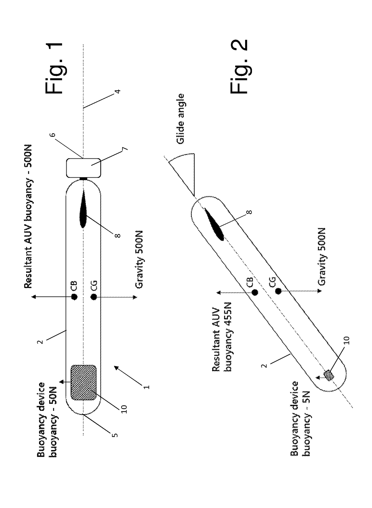
[0033]An autonomous underwater vehicle (AUV) 1 shown in FIG. 1 comprises a body 2 containing a seismic sensor system (not shown). The seismic sensor system is shown in FIG. 7 which will be discussed below. The body 2 has an axis 4 which passes through a nose 5 and a tail 6 of the AUV. The AUV has a propulsion system 7 which consists of a single propeller at the tail which can be operated to create a stream of water directed away from the AUV along the axis 4. The stream of water generates a thrust force along the axis 4 to propel the AUV through the water.

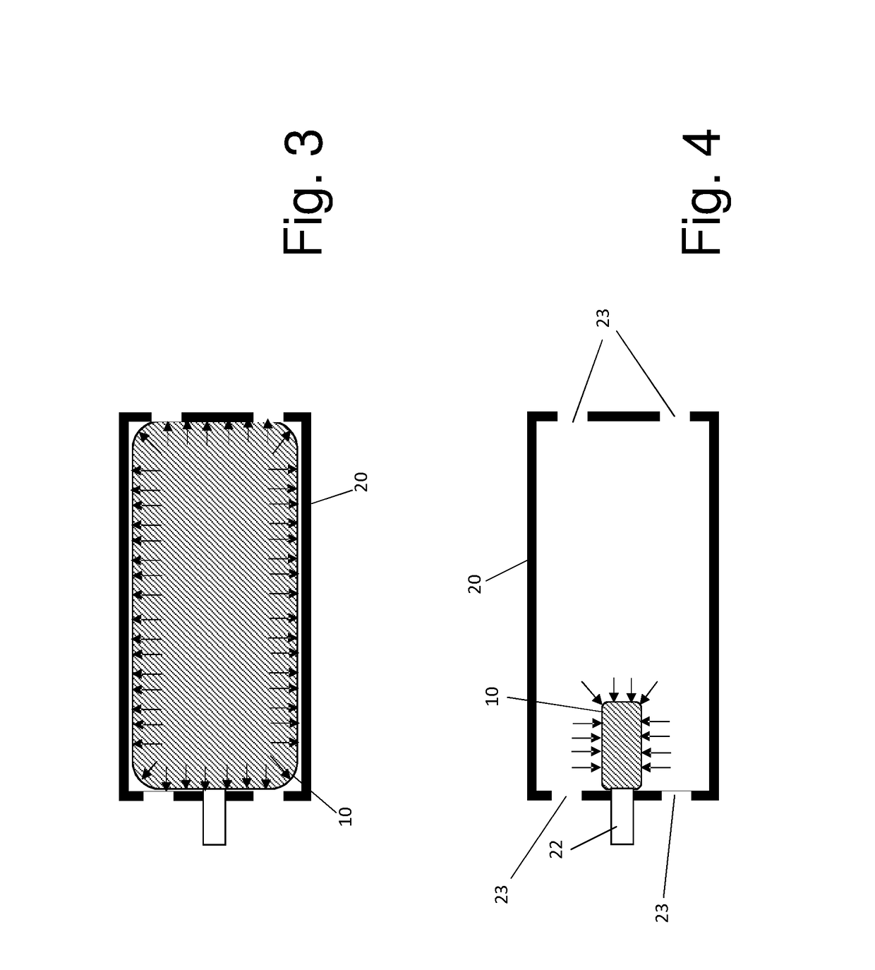
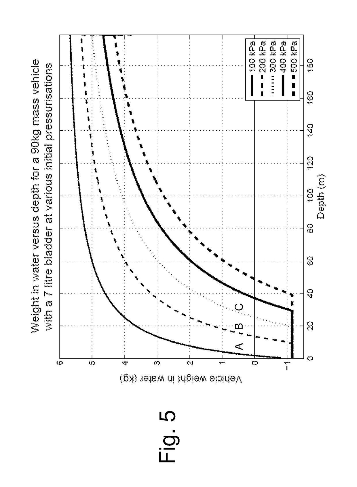
[0034]A bladder 10 is housed in the body 2 within a container 20 shown in FIGS. 3 and 4. The bladder 10 is filled with air at a desired initial sea-level pressure via a valve 22. The container has water inlet ports 23 which enable water to flow into the container to expose the bladder 10 to ambient water pressure when the AUV is submerged.

[0035]The bladder 10 provides a passive buoyancy control system. As the AUV descends, the ass...


PUM


Abstract

A method of obtaining data with a sensor of an autonomous underwater vehicle (AUV), the AUV comprising a bladder which contains a gas and is exposed to ambient water pressure. A downward thrust force is generated which causes the AUV to descend through a body of water, wherein the bladder contracts as the AUV descends due to an associated increase in the ambient water pressure, the contraction of the bladder causing the gas to compress and the AUV to become negatively buoyant. Next the AUV lands on a bed of the body of water. After the AUV has landed on the bed, the sensor is operated to obtain data with the AUV stationary and negatively buoyant and a weight of the AUV supported by the bed. After the data has been obtained, an upward thrust force is generated which overcomes the negative buoyancy of the AUV and causes the AUV to ascend through the body of water, the ascent of the AUV causing the bladder to expand due to the associated decrease in the ambient water pressure, the expansion of the bladder causing the gas to decompress and the AUV to become neutrally buoyant.

Description

FIELD OF THE INVENTION[0001]The present invention relates to a method of obtaining data with a sensor of an autonomous underwater vehicle (AUV), and an AUV for performing such a method.BACKGROUND OF THE INVENTION[0002]WO2014 / 096265 described an autonomous underwater vehicle (AUV) for recording seismic signals during a marine seismic survey. The AUV includes a body having a flush shape; a buoyancy system located inside the body and configured to control a buoyancy of the AUV while traveling underwater; a seismic sensor for recording seismic signals; and a processor connected to the buoyancy system and configured to select one of plural phases for the buoyancy system at different times of the seismic survey.[0003]The buoyancy system comprises a chamber, and in a first phase water is introduced into the chamber and air released from the chamber so that the buoyancy of the AUV becomes neutral or slightly negative and the AUV starts its journey towards a target position at the sea bottom...

Claims


Application Information

Patent Timeline
Patent Type & Authority Applications(United States)
IPC IPC(8): B63G8/00B63G8/22G05D1/04G01V1/38G01V1/18
CPCB63G8/001B63G8/22G05D1/048G01V1/3852G01V1/184B63G2008/004B63B2211/02
Inventor SMITH, CRAIG PAULHOLLOWAY, ARRAN JAMES
Owner AUTONOMOUS ROBOTICS
Why Eureka
Try Eureka