
Catalyst arrangement for industrial emissions control and method of assembling same

Active Publication Date: 2018-12-06
GENERAL ELECTRIC CO
View PDF3 Cites 2 Cited by
  • Summary
  • Abstract
  • Description
  • Claims
  • Application Information

AI Technical Summary

Benefits of technology

The patent describes a selective catalytic reduction system for industrial plants that reduces harmful emissions in exhaust gases. The system includes a frame and a plurality of catalyst elements positioned in a vertical arrangement that can be tailored to the specific needs of each industrial plant. The catalyst elements are positioned at different axial positions within the reaction duct, enhancing the efficiency of the system. The method of assembly involves placing the frame within the reaction duct and coupling the catalyst elements to the frame. The technical effects include high efficiency in reducing harmful emissions and customization for different industrial plants.

Problems solved by technology

Emissions of such pollutants into an ambient atmosphere must be limited for safe operation.
Moreover, space in industrial systems is typically limited and / or expensive, necessitating as small of a footprint as possible for the SCR system.
However, the rapid change in cross-sectional area of the inlet duct may result in flow separation and / or recirculation zones, which in turn increases pressure drop and / or non-uniformity of gas flow temperature and velocity over the catalyst.
As a result, performance of the catalyst may vary across the wall, and a useful lifetime of some catalyst elements may be reduced.

Method used


Image

  • Catalyst arrangement for industrial emissions control and method of assembling same
  • Catalyst arrangement for industrial emissions control and method of assembling same
  • Catalyst arrangement for industrial emissions control and method of assembling same

Examples


first embodiment

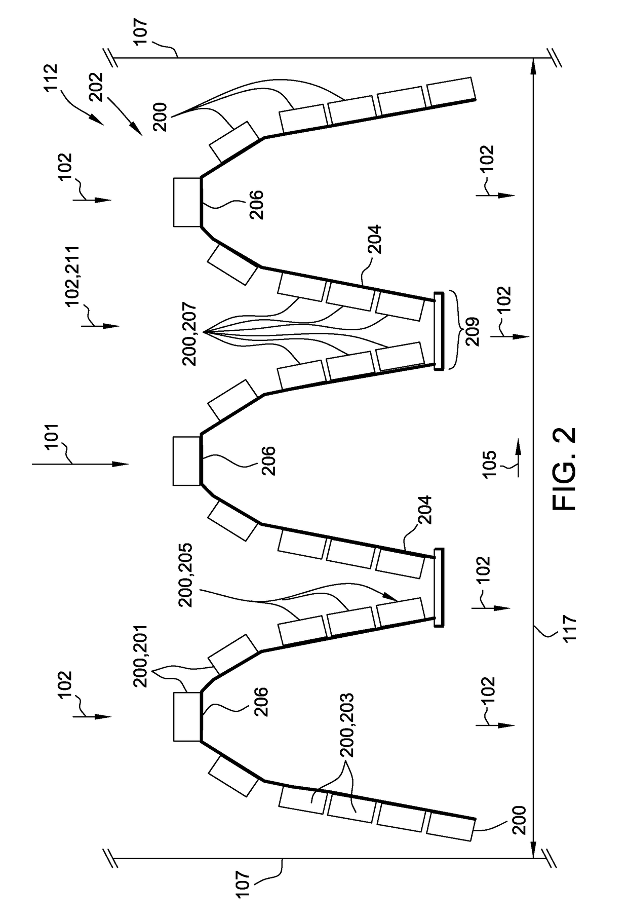
[0032]In catalyst arrangement 112 illustrated in FIG. 2, frame 204 at the illustrated vertical station 202 includes a series of transversely adjacent U-shaped sections 206, with a closed end of each U-shaped section 206 extending upstream towards the incoming flow of exhaust gases 102. Catalyst elements 200 are coupled to an upstream side of each U-shaped section 206, such that catalyst elements 200 are arranged at a plurality of axial positions, facilitating packing of an increased number of catalyst elements 200 along vertical station 202 as compared to a flat transverse wall of catalyst elements (not shown). In some embodiments, the legs of each U-shaped section 206 include at least one of catalyst element 203 positioned completely downstream from catalyst element 201, at least three catalyst elements 205 aligned in series along axial direction 101, and concentrated group 207 of catalyst elements 200 axially aligned with flow region 211 having at least one local flow characterist...

second embodiment

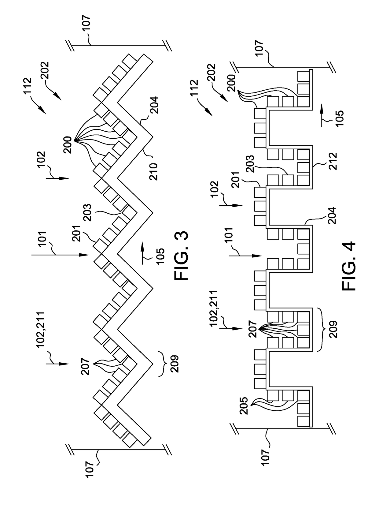
[0033]FIG. 3 is a view of a vertical station 202 of a second exemplary embodiment of catalyst arrangement 112. In catalyst arrangement 112 illustrated in FIG. 3, frame 204 at the illustrated vertical station 202 includes a transversely extending sawtooth shape 210. Catalyst elements 200 are coupled to an upstream side of sawtooth shape 210, such that catalyst elements 200 are arranged at a plurality of axial positions, facilitating packing of an increased number of catalyst elements 200 along vertical station 202 as compared to a flat transverse wall of catalyst elements (not shown). In some embodiments, the downstream vertices of sawtooth shape 210 include at least one of catalyst element 203 positioned completely downstream from catalyst element 201 and concentrated group 207 of catalyst elements 200 axially aligned with flow region 211 having at least one local flow characteristic of exhaust gases 102 incident at vertical station 202.

third embodiment

[0034]FIG. 4 is a view of a vertical station 202 of a third exemplary embodiment of catalyst arrangement 112. In catalyst arrangement 112 illustrated in FIG. 4, frame 204 at the illustrated vertical station 202 includes a transversely extending square-wave shape 212. Catalyst elements 200 are coupled to an upstream side of square-wave shape 212, such that catalyst elements 200 are arranged at a plurality of axial positions, facilitating packing of an increased number of catalyst elements 200 along vertical station 202 as compared to a flat transverse wall of catalyst elements (not shown). In some embodiments, the axially extending portions of square-wave shape 212 include at least one of catalyst element 203 positioned completely downstream from catalyst element 201, at least three catalyst elements 205 aligned in series along axial direction 101, and concentrated group 207 of catalyst elements 200 axially aligned with flow region 211 having at least one local flow characteristic of...


PUM


Abstract

A catalyst arrangement for use with a selective catalytic reduction system includes a frame and a plurality of catalyst elements coupled to the frame. The plurality of catalyst elements is arranged vertically among a plurality of vertical stations. The plurality of vertical stations is successively defined along a height of the catalyst arrangement. The catalyst elements of at least one of the vertical stations are arranged at a plurality of axial positions with respect to an axial direction of a flow of exhaust gases through the selective catalytic reduction system.

Description

BACKGROUND[0001]The embodiments described herein relate generally to industrial emissions control systems and, more particularly, to an arrangement for a catalyst in an industrial emissions control system.[0002]At least some know industrial systems that combust hydrocarbon fuels, such as gas turbines, industrial boilers and furnaces, and reciprocating engines, generate pollutants such as, but not limited to, carbon monoxide (CO), unburned hydrocarbons (UHC), and oxides of nitrogen (NOx). Emissions of such pollutants into an ambient atmosphere must be limited for safe operation.[0003]One known technology for use in controlling stack emissions is Selective Catalytic Reduction. Selective Catalytic Reduction (SCR) is a method of reducing an amount of NOx and CO in the exhaust gas of fossil fuel-fired industrial and electric utility equipment. In at least some known SCR systems, anhydrous ammonia is mixed with the exhaust gas, and the mixture is channeled over a suitable reduction cataly...

Claims


Application Information

Patent Timeline
IPC IPC(8): F01N3/20F01N3/28F01N13/18B01J23/22B01J35/04B01D53/88B01D53/86
CPCF01N3/2066F01N3/2892F01N13/18B01J23/22B01J35/04B01D2255/20723B01D53/8631B01D53/864B01D53/8653F01N2370/02B01D53/885B01D53/86B01D53/8628B01D53/88B01D53/9418B01D2251/2062B01D2258/012B01D2258/0283B01D2255/20707F01N2610/02Y02T10/12
Inventor SARASWATHI, RAJESH PRABHAKARANKIPPEL, BRADLY AARON
Owner GENERAL ELECTRIC CO
Learn More