Air cleaner

a technology for air cleaners and air outlet pipes, which is applied in the direction of air cleaners for fuel, charge feed systems, combustion engines, etc., can solve the problems of unstable airflow in the outlet pipes, and achieve the effects of reducing manufacturing costs, suppressing airflow separation and deflection, and stable stream

Active Publication Date: 2018-12-06
TOYOTA JIDOSHA KK
View PDF0 Cites 2 Cited by
  • Summary
  • Abstract
  • Description
  • Claims
  • Application Information

AI Technical Summary

Benefits of technology

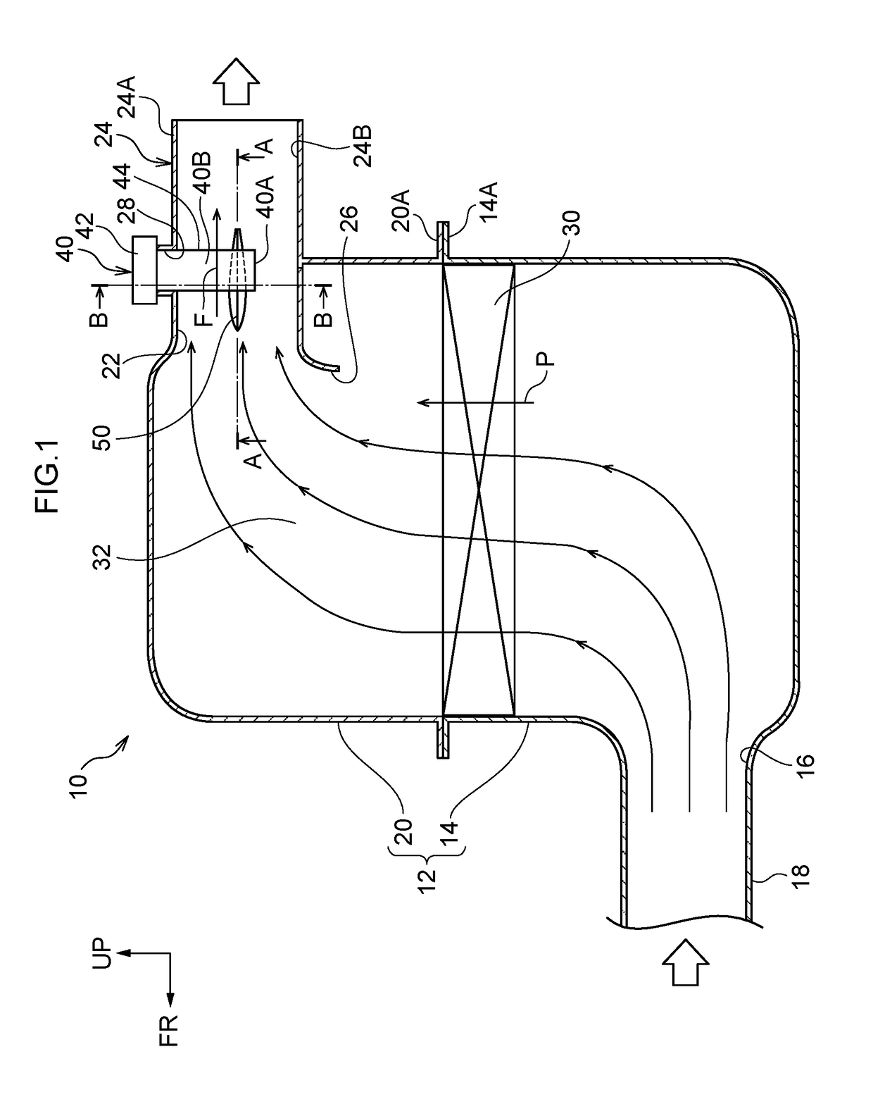
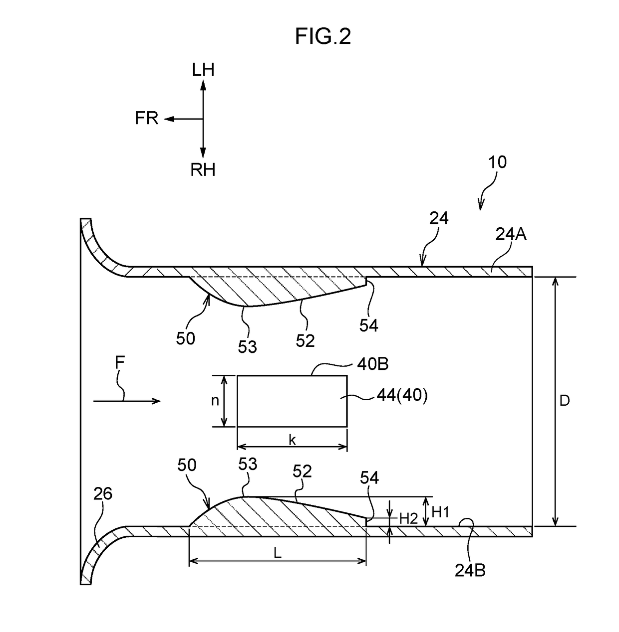
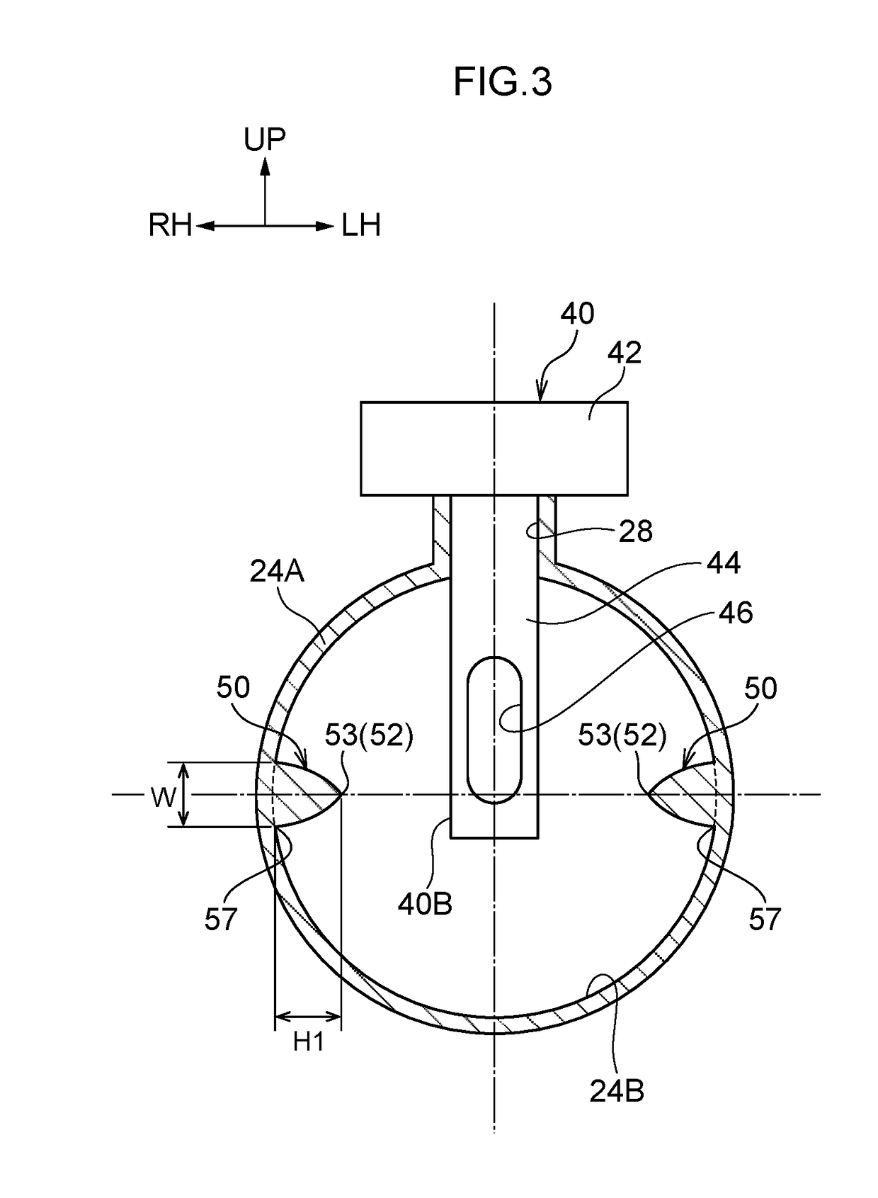
The present invention relates to an air cleaner that reduces airflow separation and deflection in an outlet pipe, allowing a stable stream of air to flow into an airflow meter. The air cleaner includes flow-regulating members with a cross-section profile resembling an airfoil, which are positioned on the inner surface of the outlet pipe to improve the flow-regulating effect. The flow-regulating members help to align the airflow and reduce airflow separation, resulting in a more stable airflow. Additionally, the invention allows for the flow-regulating member to be integrally formed to the outlet pipe using a two-part split mold, reducing manufacturing costs. Overall, the air cleaner improves the performance and efficiency of airflow meters in industrial applications.

Problems solved by technology

When such airflow separation and deflection occurs, airflow within the outlet pipe becomes unstable, introducing variation into the quantity of air measured by the airflow meter.

Method used


Image

  • Air cleaner
  • Air cleaner
  • Air cleaner

Examples


modified examples

[0069]Explanation follows regarding modified examples that exhibit similar operation and advantageous effects as the exemplary embodiment,

first modified example

[0070]As illustrated in FIG. 8A and FIG. 8B, a first modified example includes a flow-regulating member 50A of a different shape than in the exemplary embodiment. Note that in FIG. 8A and FIG. 8B, configuration having the same functionality as for the flow-regulating members 50 of the exemplary embodiment is given the same reference numeral.

[0071]As illustrated in FIG. 8A, as seen from underneath, an edge 52 of the flow-regulating member 50A is formed with a peaked shape that linearly increases in height from a ground plane (inner surface 24B) and then linearly decreases in height on progression downstream in the direction of flow F of air, namely, on progression toward the device rear. Similarly to in the exemplary embodiment, a rear end 54 of the flow-regulating member 50A is shaped perpendicularly cut sharply toward the ground plane (inner surface 24B) at the device-rear end of the edge 52. As illustrated in FIG. 8B, as seen from the side, the flow-regulating member 50A includes ...

second modified example

[0073]As illustrated in FIG. 9A and FIG. 9B, a second modified example includes a flow-regulating member 50B of a different shape than in the exemplary embodiment. Note that in FIG. 9A and FIG. 9B, configuration having the same functionality as for the flow-regulating members 50 of the exemplary embodiment is given the same reference numeral.

[0074]As illustrated in FIG. 9A, as seen from underneath, an edge 52 of the flow-regulating member 50B is formed with a peaked shape that linearly increases in height from a ground plane (inner surface 24B) and then linearly decreases in height on progression downstream in the direction of flow F of air, namely, on progression toward the device rear. Similarly to in the exemplary embodiment, a rear end 54 of the flow-regulating member 50B is shaped perpendicularly cut sharply toward the ground plane (inner surface 24B) at the device-rear end of the edge 52. Further, as illustrated in FIG. 9B, as seen from the side, the flow-regulating member 50B...


PUM


Abstract

There is provided an air cleaner including: an outlet pipe through which air is discharged; an airflow meter that is inserted toward an interior of the outlet pipe through a wall of the outlet pipe; and a flow-regulating member that is formed projecting from an inner surface of the outlet pipe at a side of the airflow meter, the flow-regulating member including an edge that is formed with a peaked shape with respect to the inner surface and that runs along a direction of flow of air, a rear end that is formed at a downstream end of the edge in the direction of flow, and that is shaped cut sharply toward the inner surface and a width-narrowing portion that decreases in width in a circumferential direction of the outlet pipe on progression downstream in the direction of flow.

Description

CROSS-REFERENCE TO RELATED APPLICATION[0001]This application is based on and claims priority under 35 USC 119 from Japanese Patent Application No. 2017-110365 filed on Jun. 2, 2017, the disclosure of which is incorporated by reference herein.BACKGROUNDTechnical Field[0002]The present disclosure relates to an air cleaner.Related Art[0003]Japanese Patent Application Laid-Open (JP-A) No. 2000-303921 discloses an air cleaner. In this air cleaner, an airflow meter is inserted into an outlet pipe (air lead-out passage cylinder) integrally formed to a cap that is part of a housing that houses a filter element, and a tubular flow-regulating member is provided upstream of the airflow meter.[0004]However, in cases in which an airflow meter projects into an outlet pipe such as in the air cleaner of JP-A 2000-303921, airflow separation and deflection is caused by the airflow meter inside the outlet pipe.[0005]When such airflow separation and deflection occurs, airflow within the outlet pipe bec...

Claims


Application Information

Patent Timeline
IPC IPC(8): F02M35/10F02M35/04F02M35/02F02M35/024
CPCF02M35/10262F02M35/048F02M35/0207F02M35/044F02M35/024F02M35/0201F02M35/0204F02M35/0209F02M35/10006Y02T10/12
Inventor HARADA, AKIRARIKITAKE, SHUNSUKE
Owner TOYOTA JIDOSHA KK
Why Eureka
Try Eureka