Control rod drive system and inspection method of control rod drive system

a technology of control rods and drive systems, which is applied in the direction of nuclear engineering problems, nuclear elements, greenhouse gas reduction, etc., can solve the problems of difficult to maintain the reliability of inspection to be sufficiently high, a large amount of time and effort required for work,

Active Publication Date: 2018-12-13
HITACHI-GE NUCLEAR ENERGY LTD
View PDF0 Cites 0 Cited by
  • Summary
  • Abstract
  • Description
  • Claims
  • Application Information

AI Technical Summary

Benefits of technology

The present invention allows for inspecting the first hydraulic control unit without affecting the function of the control rod drive mechanisms. This is achieved by supplying hydraulic pressure to the control rod drive mechanisms through the second hydraulic control unit instead of the first hydraulic control unit.

Problems solved by technology

Therefore, a great deal of trouble and time are required for work of taking out the fuel for the inspection and repair work after the inspection in related art.
However, there is a time limit when inspection is performed in the operation period of the reactor because of constraints of safety regulations, therefore, it is necessary to perform inspection quickly with respect to one hydraulic control unit.
As there are many inspection items in the hydraulic control unit, it may be difficult to maintain reliability in inspection to be sufficiently high if work time for the inspection is limited.

Method used


Image

  • Control rod drive system and inspection method of control rod drive system
  • Control rod drive system and inspection method of control rod drive system
  • Control rod drive system and inspection method of control rod drive system

Examples


example 1

[0022]A first example will be explained with reference to FIG. 1 to FIG. 6. The following example is one example and the present invention is not limited to a configuration of the example.

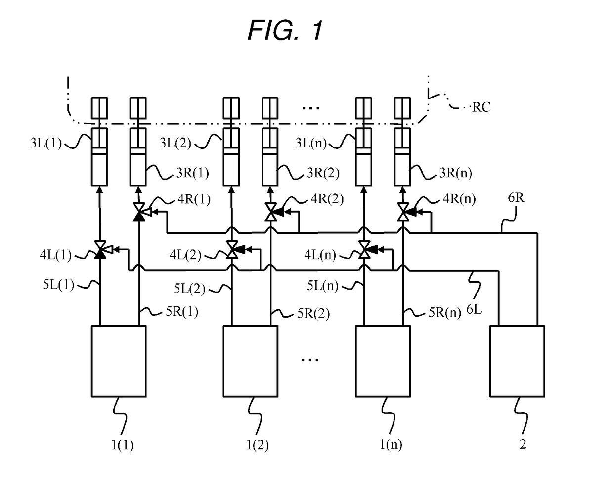
[0023]FIG. 1 is an entire configuration diagram of the control rod drive system. The control rod drive system includes, for example, a plurality of hydraulic control units 1(1) to 1 (n), at least one hydraulic control unit for maintenance 2, control rod drive mechanisms 3L, 3R, three-way selector valves 4L, 4R, pipes 5L, 5R and pipes for maintenance 6L, 6R.

[0024]In the following description, the hydraulic control units 1 (1) to 1 (n) may be abbreviated as the hydraulic control units 1, the control rod drive mechanisms 3L, 3R may be abbreviated as the control rod drive mechanisms 3, the three-way selector valves 4L, 4R may be abbreviated as three-way selector valves 4, the pipes 5L, 5R may be abbreviated as the pipes 5 and the pipes for maintenance 6L, 6R may be abbreviated as pipes for maintenance ...

example 2

[0050]A second example will be explained with reference to FIG. 7 and FIG. 8. The difference from the first example will be mainly described in the following respective examples including this example. In the example, tees 42 and passage selector gate valves 43 are used as given valve structures 4 (2) for connecting the hydraulic control unit for maintenance 2 to the pipes 5. When valve structures 4L (2) and 4R (2) may be abbreviated as valve structures 4 (2) when they are not distinguished.

[0051]FIG. 7 is a system diagram of a control rod drive system according to the example. In the example, the hydraulic control unit for maintenance 2 is connected through the tees 42 and the passage selector gate valves 43 between the hydraulic control unit 1 and the control rod drive mechanisms 3.

[0052]The tee 42 has three openings. A first opening is connected to the discharge port of the hydraulic control unit 1. A second opening is connected to the discharge port of the hydraulic control unit...

example 3

[0059]A third example will be explained with reference to FIG. 9 and FIG. 10. Given valve structures 4 (3) in the example are connected to maintenance pipes 6 through flange joints 44. Each flange joint 44 can be provided at a tip end of either the three-way selector valve 41 or the tee 42. In the example, a case in which the flange joint 44 is provided at the tip end of a branch of the three-way selector valve 41 will be explained as an example.

[0060]As shown in FIG. 9, opening ends of the flange joints 44 are closed by blank flanges 45 at the time of normal operation of the hydraulic control unit 1.

[0061]On the other hand, at the time of inspecting the hydraulic control unit 1, the blank flanges 45 are removed as shown in FIG. 10 and the flange joints 44 are fastened to flange joints provided at tip ends of the maintenance pipes 6.

[0062]After that, the three-way selector valves 41 are switched and the hydraulic control unit for maintenance 2 is connected to the control rod drive m...


PUM


Abstract

To provide a control rod drive system and an inspection method of the control rod drive system capable of performing inspection safely and effectively. A control rod drive system controlling operation by supplying a hydraulic pressure to control rod drive mechanisms includes a plurality of first hydraulic control units supplying the hydraulic pressure to corresponding given control rod drive mechanisms and a second hydraulic control unit supplying the hydraulic pressure to corresponding given control rod drive mechanisms of the first hydraulic control unit as an inspection target instead of the first hydraulic control unit as the inspection target selected from the respective first hydraulic control units.

Description

BACKGROUND OF THE INVENTION1. Field of the Invention[0001]The present invention relates to a control rod drive system and an inspection method of the control rod drive system.2. Description of Related Art[0002]In general, a control rod drive mechanism is an apparatus that drives a control rod for controlling the output of a reactor, and a hydraulic control unit is an apparatus that converts an electrical signal into a hydraulic pressure and supplies a drive force to the control rod drive mechanism.[0003]For example, the control of output in a boiling-water reactor is performed by inserting or pulling out the control rods in addition to the control by a coolant. At the time of emergency stop of the reactor, high-pressure water is supplied from hydraulic control units as drive sources by the hydraulic pressure into the control rod drive mechanisms, thereby urgently inserting the control rods installed at an upper part of the control rod drive mechanisms into a fuel assembly to stop th...

Claims


Application Information

Patent Timeline
Patent Type & Authority Applications(United States)
IPC IPC(8): G21C7/16G21C17/12G21C9/02G21C15/18
CPCG21C7/16G21C17/12G21C9/02G21C15/18G21Y2002/201G21Y2004/304G21C17/10Y02E30/30
Inventor OOKA, KENTOMISAWA, NAOTOOKAZAWA, HIROSHI
Owner HITACHI-GE NUCLEAR ENERGY LTD
Why Eureka
Try Eureka