
Pan-tilt-zoom camera and unmanned aerial vehicle

Active Publication Date: 2018-12-13
SHENZHEN HUBSAN TECH
View PDF0 Cites 2 Cited by
  • Summary
  • Abstract
  • Description
  • Claims
  • Application Information

AI Technical Summary

Benefits of technology

The present patent aims to provide a PTZ camera with a compact structure, good vibration damping performance, and high use safety. The camera unit is fixedly disposed on the first vibration damper plate, which absorbs the shock when the PTZ camera is subjected to extra load other than gravity. This ensures steady photographing of the PTZ camera and exhibits good vibration reducing performance.

Problems solved by technology

However, during flying, UAVs are subjected to big shake and strong vibration.
Conventional pan-tilt units are complex in structure, large in size, and the shock absorber ball tends to loosen and fall off, causing the detachment of the pan-tilt units, which poses a hidden danger.

Method used


Image

  • Pan-tilt-zoom camera and unmanned aerial vehicle
  • Pan-tilt-zoom camera and unmanned aerial vehicle
  • Pan-tilt-zoom camera and unmanned aerial vehicle

Examples


Embodiment Construction

[0027]To make the technical solutions of the present invention more clear and complete, the present invention will be described in more detail with accompanying drawings.

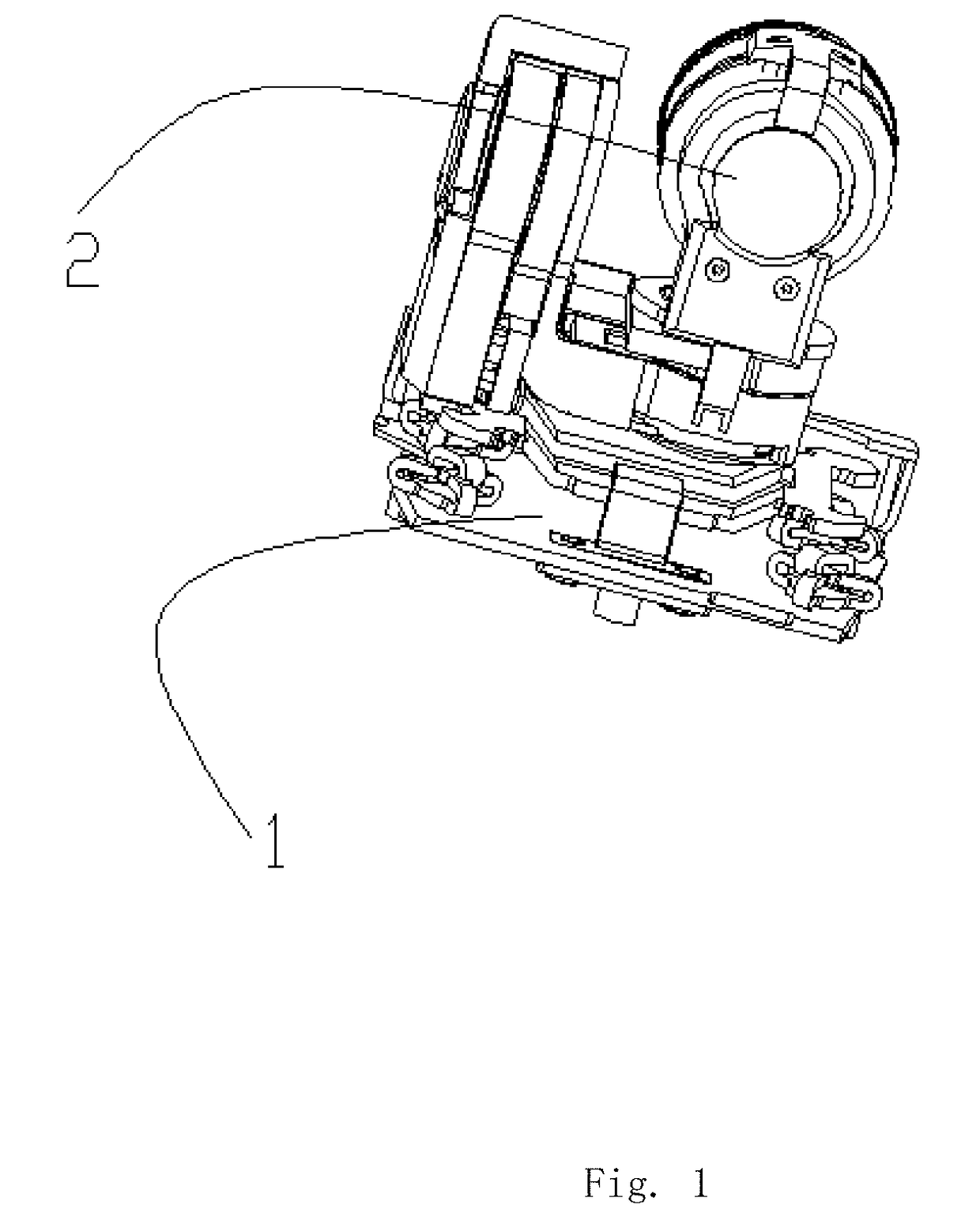
[0028]As shown in FIG. 1, one embodiment provides an unmanned aerial vehicle comprising a support part and a pan-tilt-zoom (PTZ) camera mounted on the support part. The pan-tilt-zoom (PTZ) camera comprises a pan-tilt unit 1 and a camera unit 2.

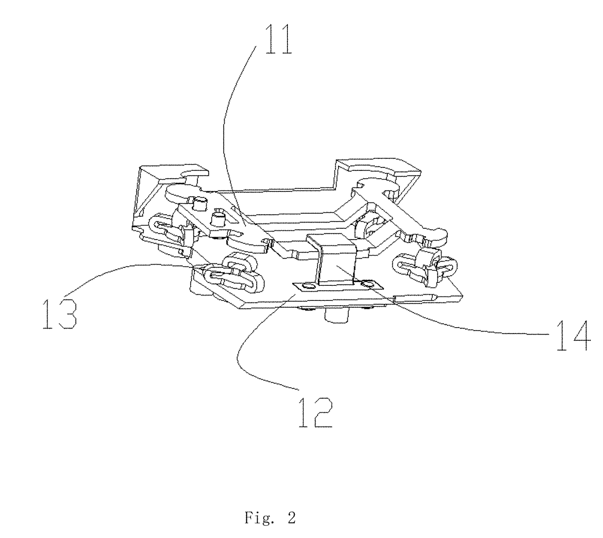
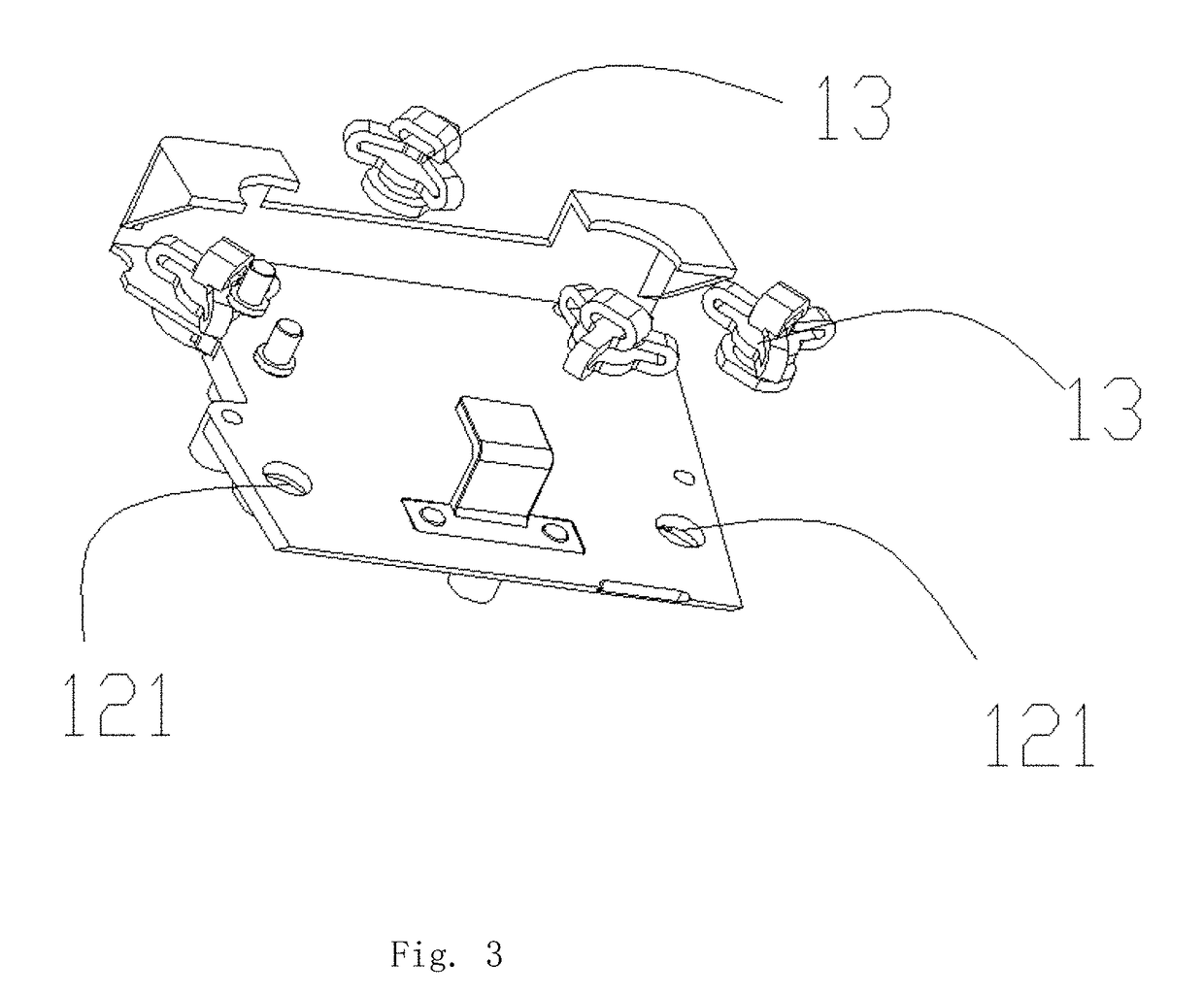
[0029]Specifically, as shown in FIG. 2, the pan-tilt unit 1 comprises a first vibration damper plate 11, a second vibration damper plate 12, and a shock absorber ball 13; the camera unit 2 is fixedly disposed on the first vibration damper plate 11, the shock absorber ball 13 is sandwiched between the first vibration damper plate 11 and the second vibration damper plate 12, and the shock absorber ball 13 is fixedly connected to the second vibration damper plate 12; the shock absorber ball 13 is elastic, and when the camera unit 2 is horizontally laid, the first vibration damper...


PUM


Abstract

The invention provides a pan-tilt-zoom (PTZ) camera, including a pan-tilt unit and a camera unit. The pan-tilt unit includes a first vibration damper plate, a second vibration damper plate, and a shock absorber ball; the camera unit is fixedly disposed on the first vibration damper plate, the shock absorber ball is sandwiched between the first vibration damper plate and the second vibration damper plate, and the shock absorber ball is fixedly connected to the second vibration damper plate; the shock absorber ball is elastic, and when the camera unit is horizontally laid, the first vibration damper plate is out of touch with the shock absorber ball; when the camera unit is subjected to extra load other than gravity, the first vibration damper plate compresses the shock absorber ball. The pan-tilt unit of the invention is simple in structure and safe in use. The camera unit is fixedly disposed on the first vibration damper plate, when the PTZ camera is subjected to extra load other than gravity, the shock absorber ball absorbs the shock, ensuring steady photographing of the PTZ camera, and exhibiting good vibration reducing performance.

Description

FIELD OF THE INVENTION[0001]The invention relates to the field of unmanned aerial vehicles, and more particularly to a pan-tilt-zoom (PTZ) camera and an unmanned aerial vehicle (UAV).BACKGROUND OF THE INVENTION[0002]Unmanned aerial vehicles, UAVs for short, are unmanned aircrafts controlled by radio remote equipment and self-contained program control devices. With advantages of small size, light weight, low costs, flexible operation, and high safety, UAVs are widely used for such fields as aerial photography, detection, search and rescue, resource exploration, and the like. However, during flying, UAVs are subjected to big shake and strong vibration. To ensure the quality of the aerial photo graph and protect the aerial equipment, a pan-tilt unit is employed to coordinate with the aerial equipment to improve the flight stability. Conventional pan-tilt units are complex in structure, large in size, and the shock absorber ball tends to loosen and fall off, causing the detachment of th...

Claims


Application Information

Patent Timeline
IPC IPC(8): H04N5/225B64C39/02B64D47/08H04N5/232
CPCH04N5/2253B64C39/024B64D47/08B64C2201/127H04N5/23296H04N5/23264H04N5/2254G03B17/561B64U2101/30B64U20/87H04N23/50H04N23/55H04N23/695H04N23/54H04N23/69H04N23/682
Inventor CHEN, GUANGYAOPANG, FANLILIU, SHENGLONG
Owner SHENZHEN HUBSAN TECH
Learn More