
Closed loop roller leveler with oscillating laser sensors

Inactive Publication Date: 2018-12-20
BUTECH INC D B A BUTECH BLISS
View PDF0 Cites 2 Cited by
  • Summary
  • Abstract
  • Description
  • Claims
  • Application Information

AI Technical Summary

Benefits of technology

The patent describes a system for measuring the flatness of a strip of material. The system uses force and distance sensors to measure the load on the material. The system is designed to be easy to maintain and can self-monitor and adjust to prevent damage to the force sensors. The system also uses a laser sensor to provide a more complete map of the flatness of the material and helps to interpret the force reaction of the material edges. The system can operate automatically over a wide range of strip thickness and yield strength combinations, eliminating the need for operator intervention.

Problems solved by technology

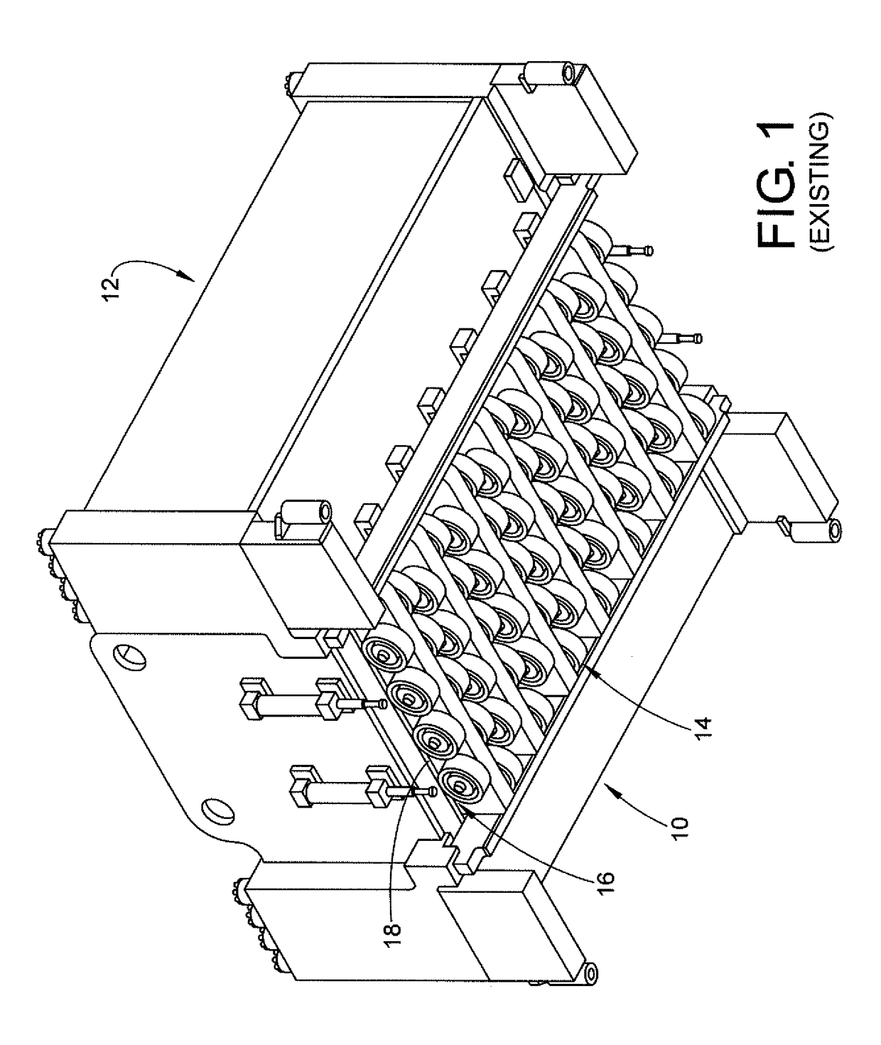
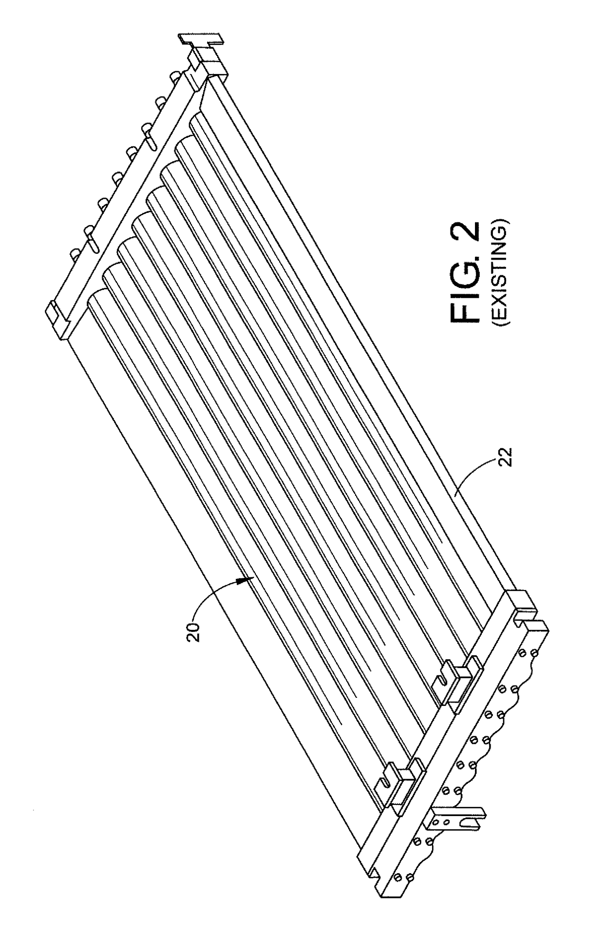
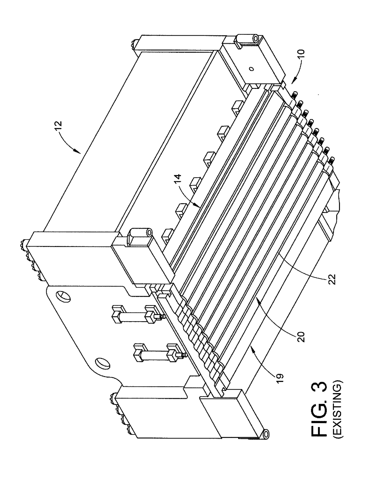
There are existing automatic closed loop control levelers but a problem with them is the sensing systems are expensive and are not capable of covering the entire range of strip thickness, strip width and yield strength that a leveler could process.
Another problem is the flatness sensors are difficult to maintain requiring lengthy outages resulting in loss of production.

Method used


Image

  • Closed loop roller leveler with oscillating laser sensors
  • Closed loop roller leveler with oscillating laser sensors
  • Closed loop roller leveler with oscillating laser sensors

Examples


Embodiment Construction

[0047]Referring to FIG. 6, a flatness sensor 40 in accordance with a preferred embodiment is shown. A roller leveler 42 has the flatness sensor 40 downstream and installed in a process line. The strip 44 is under tension as it travels in direction T and passes over the flatness sensor. At lighter gauges, the tension is enough to make the wavy strip look flat, but it will become wavy when tension is removed.

[0048]Referring now to FIG. 7, flatness sensor 40 is shown not engaged to the strip 44. Two hydraulic cylinders 46 are used to lift the flatness sensor into operating position. As shown, hydraulic cylinders 46, lift the flatness sensor straight up and down, but the mechanism can also be designed to lift the sensors in a pivoting fashion. Sensing rollers 48 would be individually mounted on their own pivot brackets. The entire array of sensors would be moved up and down by hydraulic cylinders 46.

[0049]Load cells 50 of sensor 40 are shown as compact puck style, which is the preferred...


PUM

PropertyMeasurementUnit
Widthaaaaaaaaaa
Distanceaaaaaaaaaa

Abstract

A closed loop roller leveler assembly for measuring flatness of a strip, having a roller leveler, a flatness sensor, and at least one arm operatively connected to the flatness sensor to raise and lower the flatness sensor. The flatness sensor has a plurality of sensor rolls, at least one load cell, and at least one laser sensor which is mounted on a positioner which oscillates the laser sensors across a width of the strip.

Description

CLAIM OF PRIORITY[0001]This application claims priority from U.S. Provisional Patent Application Ser. No. 62 / 520,224 filed on Jun. 15, 2017, the entirety of which is hereby incorporated by reference.BACKGROUND OF THE DISCLOSURE[0002]The disclosure relates to roller levelers. More particularly it relates to a roller leveler that operates in a closed loop automatic control mode.[0003]A metal strip product is fed into a roller leveler, typically from a coil. Roller levelers use multiple work rolls to flatten the strip. The path of the strip passes between offset upper and lower work rolls, which reverse bend the strip multiple times before the strip exits the leveler.[0004]A given roller leveler is designed to process a range of strip thicknesses and strip yield strengths. As the strip passes between the work rolls very high separating forces are generated against the work roll face, yet the work roll diameters are of necessity relatively small; this to allow the work rolls to bend and...

Claims


Application Information

Patent Timeline
IPC IPC(8): B21B37/36B21D1/02B21B37/16B21B15/00
CPCB21B37/36B21D1/02B21B37/165B21B15/00B21B2015/0071B21B2263/06B21B2263/08B21B38/02
Inventor GAMBLE, NATHANIEL H.LATHAM, TONYCUFF, JASONORZEL, EDWARD S.
Owner BUTECH INC D B A BUTECH BLISS
Learn More