Housing of fire emergency indicating light
a technology for emergency lighting and fire, applied in the field of emergency lighting equipment, can solve the problems of high cost and long molding time of metal parts, and still occur electric leakage accidents, etc., and achieve the effects of short molding time, easy recycling and simple production process
- Summary
- Abstract
- Description
- Claims
- Application Information
AI Technical Summary
Benefits of technology
Problems solved by technology
Method used
Image

Examples
embodiment 1
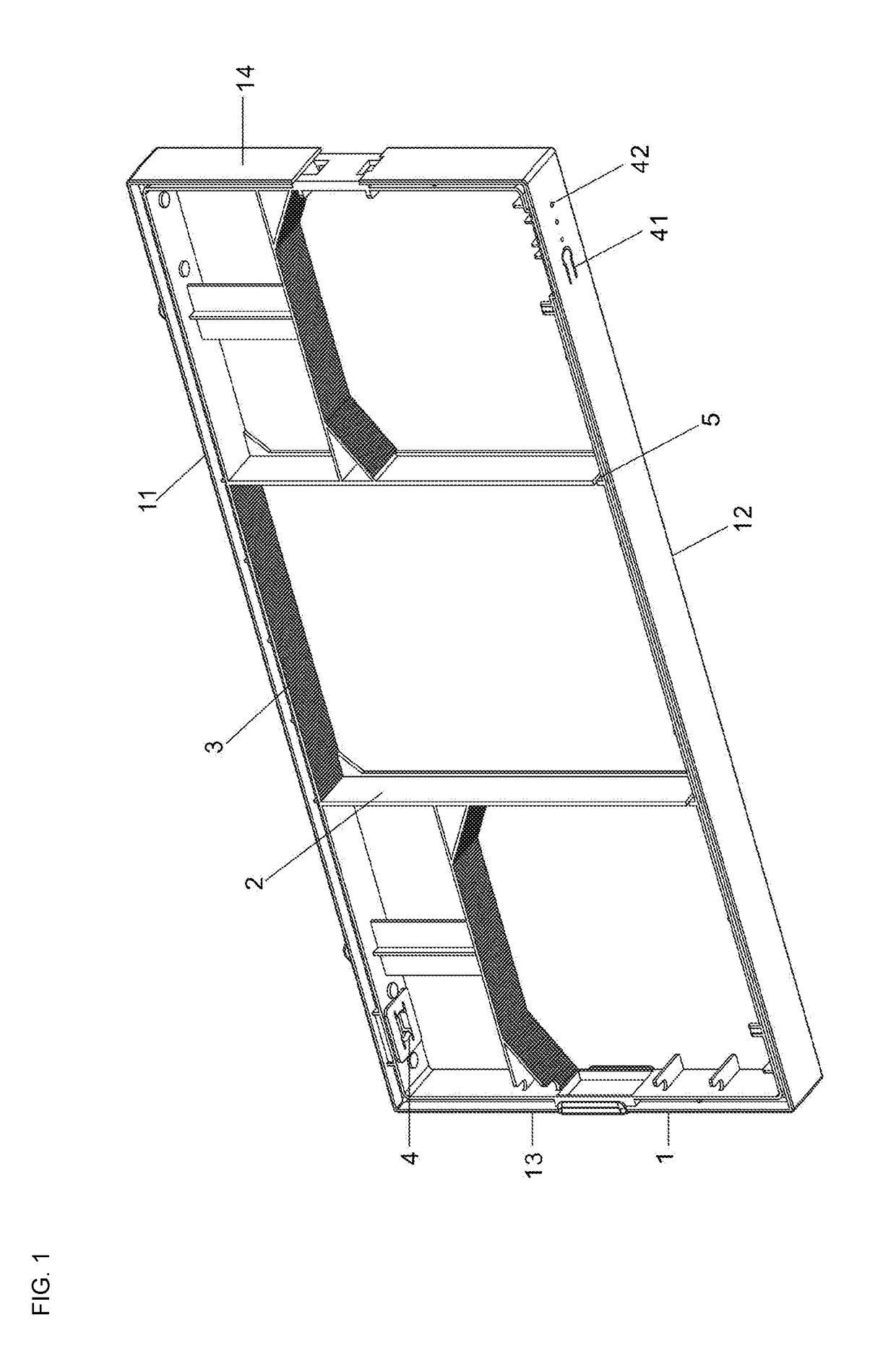
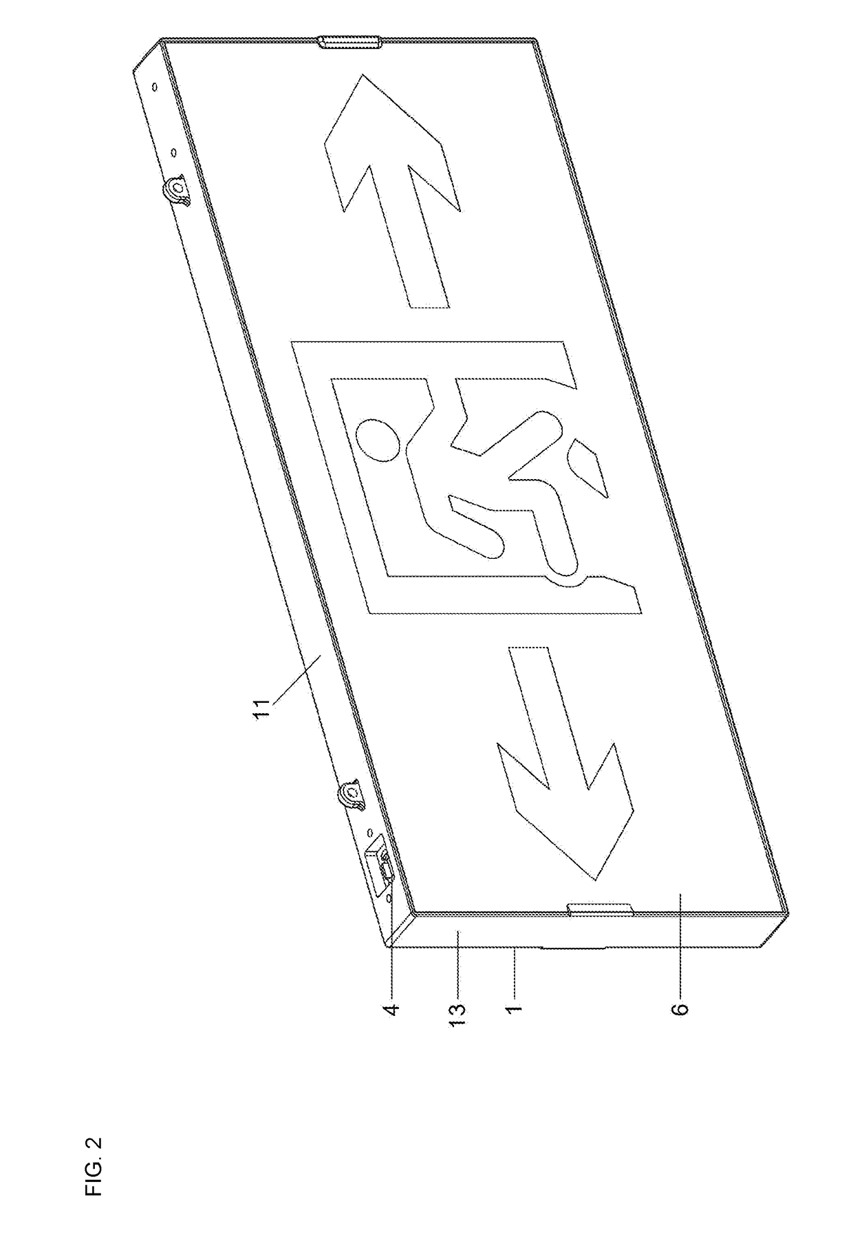
[0014]As shown in FIG. 1 and FIG. 2, the present invention provides a housing of a fire emergency indicating light, wherein the housing is molded from fireproof plastics through one processing and includes a rectangle-shaped frame 1, a reflective plate 2 configured in the frame 1, and a refractive plate 3 configured in the frame 1. The frame 1 can be divided into an upper frame 11, a lower frame 12, a left frame 13 and a right frame 14, wherein the upper frame 11 is provided with an outlet hole 4, the lower frame 12 is provided with a through hole 41 and a control button 42, the reflective plate 2 is connected with the upper frame 11 and the lower frame 12 in a vertical manner, and divides the housing into a left irradiated area, a middle irradiated area and a right irradiated area, a gap is formed between the reflective plate 2 and the lower frame 12 to form a plate clamping position 5, and the refractive plate 3 is arranged in the three irradiated areas.
[0015]When a circuit board ...
embodiment 2
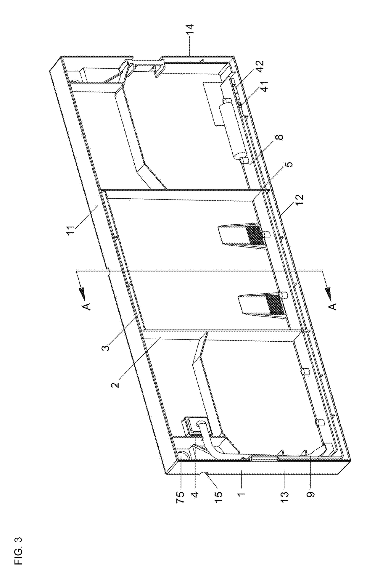
[0016]As shown in FIG. 3, FIG. 4 and FIG. 5, the present invention provides a housing of a fire emergency indicating light, wherein the housing is molded from fireproof plastics through one processing and includes a rectangle-shaped frame 1, a reflective plate 2 configured in the frame 1, and a refractive plate 3 configured in the frame 1. The frame 1 can be divided into an upper frame 11, a lower frame 12, a left frame 13 and a right frame 14, wherein the lower frame 12 is provided with a through hole 41 and a control button 42, the reflective plate 2 is connected with the upper frame 11 and the lower frame 12 in a vertical manner, and divides the housing into a left irradiated area, a middle irradiated area and a right irradiated area, a gap is formed between the reflective plate 2 and the lower frame 12 to form a plate clamping position 5, and the refractive plate 3 is arranged in the three irradiated areas; the back face of the frame 1 is further provided with an inclined plate ...
PUM
 Abstract
Description
Claims
Application Information
 - Generate Ideas
- Intellectual Property
- Life Sciences
- Materials
- Tech Scout
- Unparalleled Data Quality
- Higher Quality Content
- 60% Fewer Hallucinations
Browse by: Latest US Patents, China's latest patents, Technical Efficacy Thesaurus, Application Domain, Technology Topic, Popular Technical Reports.
© 2025 PatSnap. All rights reserved.Legal|Privacy policy|Modern Slavery Act Transparency Statement|Sitemap|About US| Contact US: help@patsnap.com