Three-dimensional printing apparatus

a three-dimensional printing and printing apparatus technology, applied in the direction of additive manufacturing processes, manufacturing tools, layer means, etc., can solve the problems of affecting the quality of the resulting three-dimensional object, clogging the nozzle hole arranged in the lower surface of the discharge head, and the peripheral portion of the powder material to swirl up and adhere, so as to prevent the defect of the three-dimensional object from affecting the quality of the result, reduce or prevent the adhesion of the powder material, and prevent the d

Inactive Publication Date: 2018-12-27
ROLAND DG CORP
View PDF7 Cites 2 Cited by
  • Summary
  • Abstract
  • Description
  • Claims
  • Application Information

AI Technical Summary

Benefits of technology

[0007]The three-dimensional printing apparatus described above operates such that the air supplier supplies air to the lower surface of the line head (i.e., to a space defined between the line head and the powder material placed on the printing table) so as to produce an air current. The air current carries away swirling-up particles of the powder material before the swirling-up particles of the powder material adhere to the lower surface of the line head. Thus, the three-dimensional printing apparatus reduces or prevents adhesion of the powder material to the line head.
[0008]A three-dimensional printing apparatus according to a preferred embodiment of the present invention effects printing with high accuracy while preventing a defective condition such as clogging of the discharge holes of the line head.
[0009]A three-dimensional printing apparatus according to a preferred embodiment of the present invention reduces the frequency of performing maintenance of the line head so as to increase the lifetime of the line head.

Problems solved by technology

Thus, discharging the curing liquid onto the powder material in the course of performing the additive manufacturing method unfortunately causes a peripheral portion of the powder material to swirl up and adhere to the lower surface of the discharge head.
The adhesion of the powder material to the discharge head may clog nozzle holes arranged in the lower surface of the discharge head.
Such a defective condition may affect the quality of a resulting three-dimensional object.
In such a case, the powder material cannot be easily removed from the lower surface of the discharge head by automatic maintenance performed afterward.
Such a line head has a long length and is prone to catch swirling-up powder accordingly.
Thus, a powder material is unfavorably more likely to adhere to such a line head than to a “shuttle head” (which may also be referred to as a “serial head”) having a length sufficiently shorter than the width of a printing region.

Method used


Image

  • Three-dimensional printing apparatus
  • Three-dimensional printing apparatus
  • Three-dimensional printing apparatus

Examples


Embodiment Construction

[0017]Preferred embodiments of the present invention will be described below with reference to the drawings. The preferred embodiments described below are naturally not intended to limit the present invention in any way. Components or elements having the same functions are identified by the same reference signs, and description thereof will be simplified or omitted when deemed redundant.

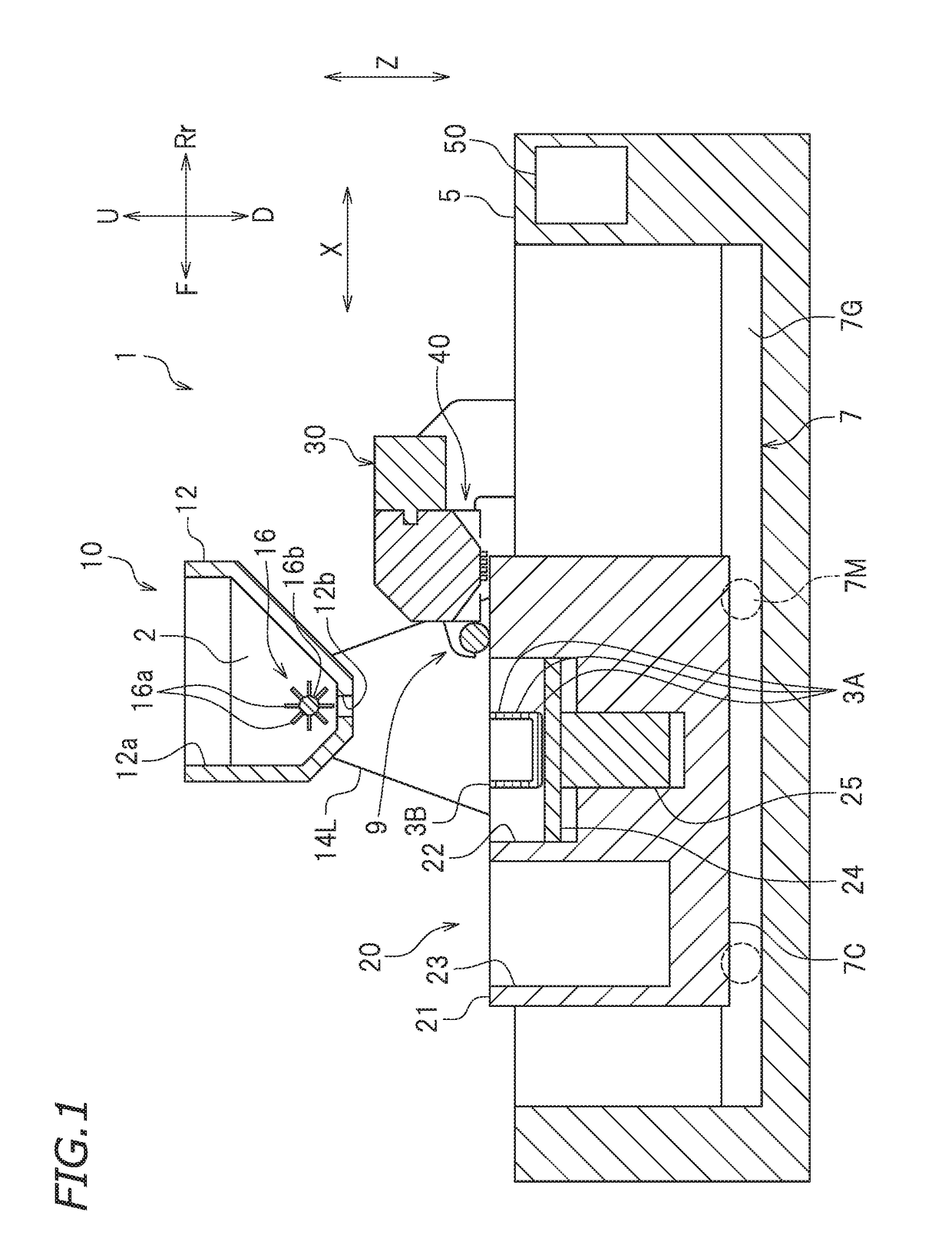
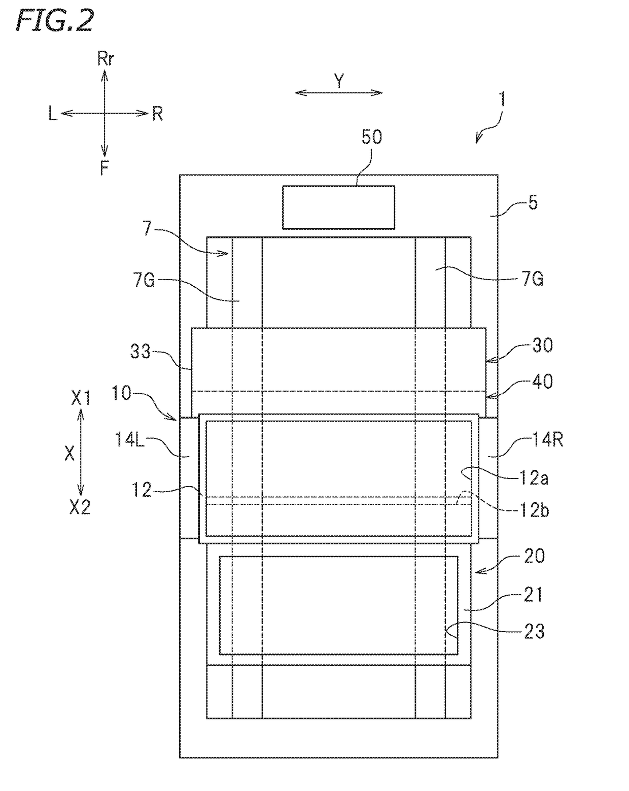
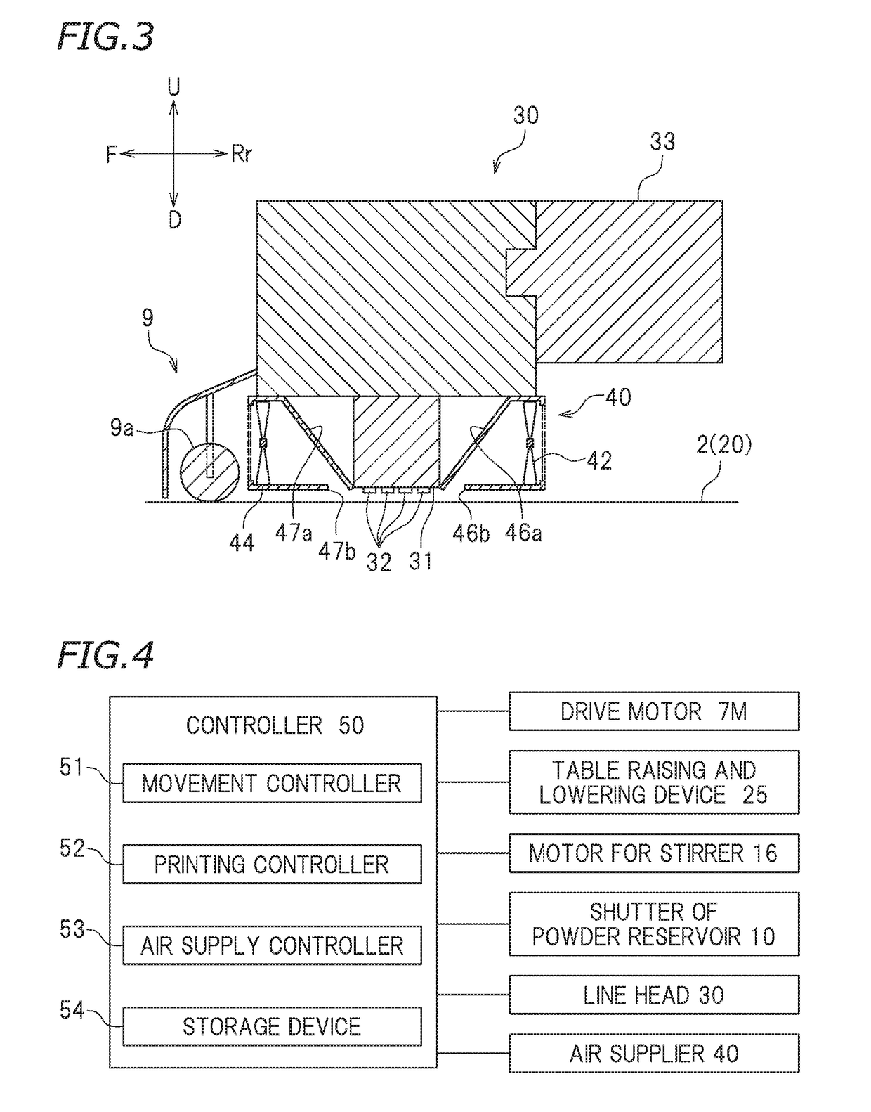
[0018]FIG. 1 is a cross-sectional view of a three-dimensional printing apparatus 1. FIG. 2 is a plan view of the three-dimensional printing apparatus 1. FIG. 3 is an enlarged cross-sectional view of a line head 30, a flattener 9, and an air supplier 40 (which will be described below). The reference signs F, Rr, R, L, U, and D in the drawings respectively represent front, rear, right, left, up, and down. The reference signs F, Rr, U, and D in the drawings may respectively represent a front side, a rear side, an upper side, and a lower side. The reference signs F, Rr, U, and D in the drawings may respe...


PUM

PropertyMeasurementUnit
distanceaaaaaaaaaa
velocityaaaaaaaaaa
velocityaaaaaaaaaa

Abstract

A three-dimensional printing apparatus includes a printing table, a line head, a conveyor, an air supplier, and a controller. The line head includes discharge holes disposed in a straight line in a first direction intersecting a scanning direction. The air supplier supplies air to a lower surface of the line head in a second direction intersecting the first direction such that the air is supplied from a rear side to a front side in the scanning direction when the line head moves relative to the printing table while discharging a curing liquid.

Description

CROSS REFERENCE TO RELATED APPLICATIONS[0001]This application claims the benefit of priority to Japanese Patent Application No. 2017-125393 filed on Jun. 27, 2017. The entire contents of this application are hereby incorporated herein by reference.BACKGROUND OF THE INVENTION1. Field of the Invention[0002]The present invention relates generally to three-dimensional printing apparatuses, and in particular, to a three-dimensional printing apparatus to effect three-dimensional printing (which may hereinafter be referred to as “additive manufacturing”) using a powder material.2. Description of the Related Art[0003]A powder lamination manufacturing technique known in the related art involves: curing, with a curing liquid, a powder material spread into a thin layer so as to form each of cross-sectional layers; and sequentially stacking the cross-sectional layers so as to print a three-dimensional object. A three-dimensional printing apparatus to perform such an additive manufacturing metho...

Claims


Application Information

Patent Timeline
Patent Type & Authority Applications(United States)
IPC IPC(8): B29C64/364B33Y30/00B33Y40/00B29C64/209B29C64/245B29C64/393B33Y50/02B29C64/255
CPCB29C64/364B33Y30/00B33Y40/00B29C64/209B29C64/245B29C64/393B33Y50/02B29C64/255B29C64/165B29K2505/00B33Y10/00B29C64/236B29C64/35
Inventor IWASE, FUMIYOSHI
Owner ROLAND DG CORP
Why Eureka
Try Eureka