Integrated aerodynamic flow control system with air source

a control system and air source technology, applied in the direction of air-flow influencers, boundary layer controls, drag reduction, etc., can solve the problems of increased weight, increased weight, and requirement of larger diameter pipes

Active Publication Date: 2018-12-27
ADVANCED FLUIDICS LLC
View PDF0 Cites 5 Cited by
  • Summary
  • Abstract
  • Description
  • Claims
  • Application Information

AI Technical Summary

Benefits of technology

[0005]In view of the foregoing, an embodiment herein provides an aerodynamic flow control system comprising a plurality of actuator units integrated at predetermined locations along a span of an aerodynamic surface of a vehicle to provide aerodynamic active air flow control, wherein each of the plurality of actuator units comprises an electrically ...

Problems solved by technology

However, implementation of this active flow control method needs a massive compressed air source unit.
Moreover, distribution of air from the source to the individual flow control actuators located far away from the compressed air source unit requires extensive fluidic plumbing, which increases weight.
Extensive plumbing also results in pressure drop along the plumbing lines resulting in requirement of larger diameter pipes.
Al...

Method used


Image

  • Integrated aerodynamic flow control system with air source
  • Integrated aerodynamic flow control system with air source
  • Integrated aerodynamic flow control system with air source

Examples


Embodiment Construction

[0025]The embodiments herein and the various features and advantageous details thereof are explained more fully with reference to the non-limiting embodiments that are illustrated in the accompanying drawings and detailed in the following description. Descriptions of well-known components and processing techniques are omitted so as to not unnecessarily obscure the embodiments herein. The examples used herein are intended merely to facilitate an understanding of ways in which the embodiments herein may be practiced and to further enable those of skill in the art to practice the embodiments herein. Accordingly, the examples should not be construed as limiting the scope of the embodiments herein.

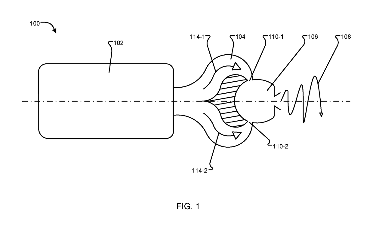
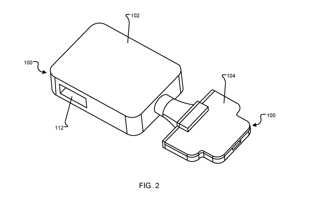
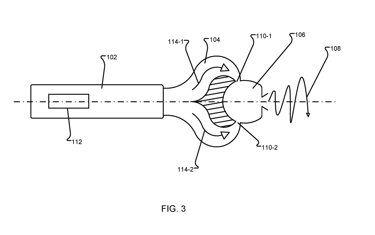
[0026]The embodiments herein provide a system and method for aerodynamic flow control that is based on compact and integrated packaging of air source and individual fluidic oscillator that produces a jet with sweeping motion. A plurality of individual fluidic oscillators, each integrated with a...


PUM


Abstract

An aerodynamic flow control system includes a plurality of actuator units integrated at predetermined locations along a span of an aerodynamic surface of a vehicle to provide aerodynamic active air flow control, wherein each of the plurality of actuator units includes an electrically powered compressor to compress air; a transitional component to receive the compressed air from the compressor and provide two streams of the compressed air; and a fluidic oscillator having two inlet ports that receive the two streams of the compressed air, and an exit port that discharges a single oscillating flow of air at a predetermined velocity.

Description

CROSS REFERENCE TO RELATED APPLICATION[0001]This application claims the benefit of U.S. Provisional Patent Application No. 62 / 522,787 filed on Jun. 21, 2017, the contents of which, in its entirety, is herein incorporated by reference.BACKGROUNDTechnical Field[0002]The embodiments herein generally relate to fluid control mechanisms, and more particularly to active flow control of air flow over an aerodynamic surface using air jets with sweeping motion.Description of the Related Art[0003]Active flow control is being pursued to improve the aerodynamic performance of an airplane, as well as unmanned aerial vehicles (UAVs). For example, it results in reduction in aerodynamic drag, increased lift during landing and take-off, and increased rudder force that results in reduction in size of vertical tail culminating in significant cost savings. Considering numerous advantages, active flow control is now considered essential during designing of future passenger and military airplanes.[0004]Ac...

Claims


Application Information

Patent Timeline
IPC IPC(8): B64C21/04
CPCB64C21/04B64C2230/18Y02T50/10
Inventor RAGHU, SURYA
Owner ADVANCED FLUIDICS LLC
Why Eureka
Try Eureka