Lighting device and lamp string
a technology of lighting device and lamp string, which is applied in the direction of light fastening, semiconductor devices for light sources, lighting and heating apparatus, etc., can solve the problems of increasing relative high cost, etc., and achieves simple operation and use safety, reduce production, maintenance and use costs, and high strength
- Summary
- Abstract
- Description
- Claims
- Application Information
AI Technical Summary
Benefits of technology
Problems solved by technology
Method used
Image
Examples
example 1
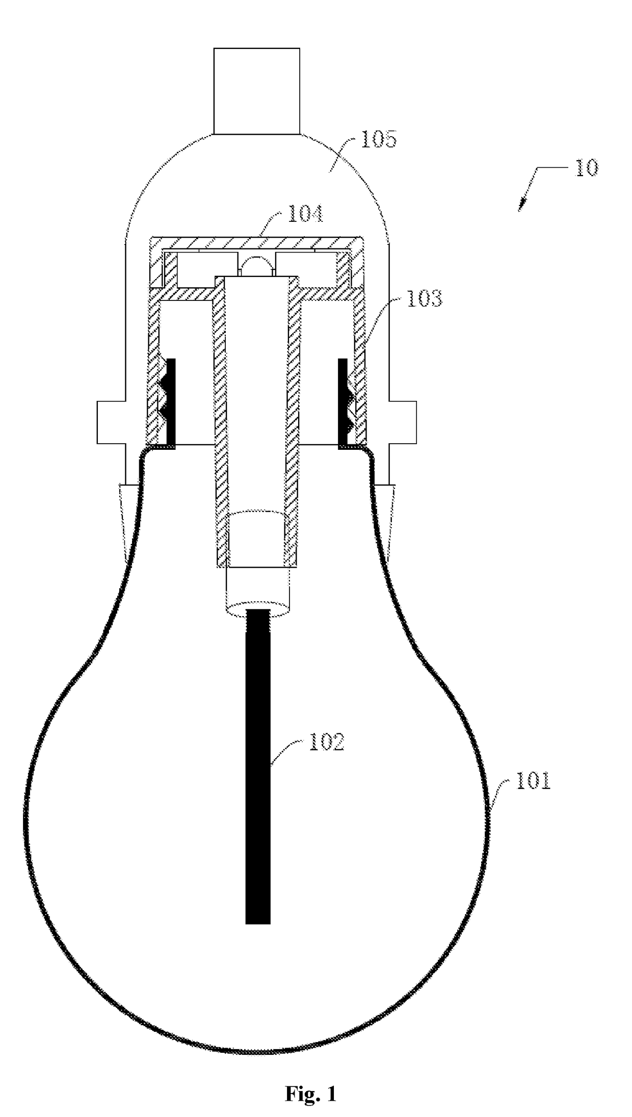
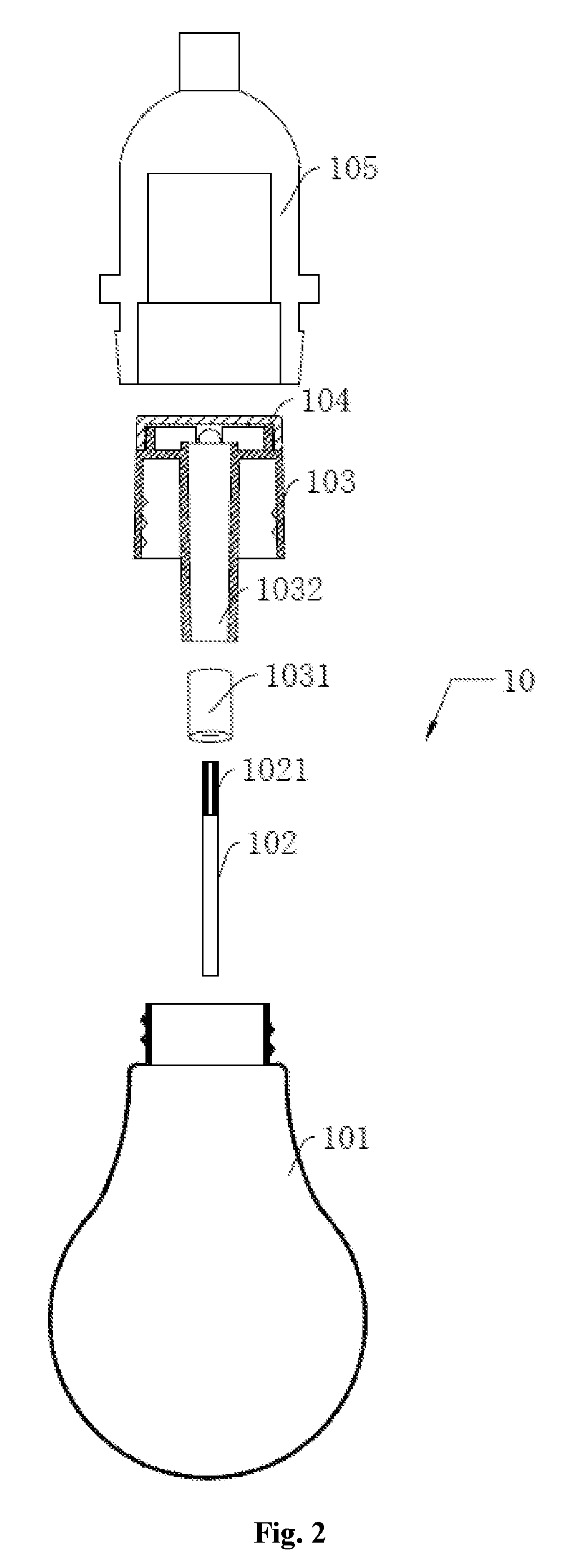
[0027]FIG. 1 shows a sectional structural schematic view of a lighting device 10, and FIG. 2 shows an exploded structural schematic view of the lighting device 10.
[0028]The lighting device 10 includes a lamp housing 101, a lighting body 102 and a lamp base 103. The lamp base 103 is detachably connected with the lamp housing 101, and the lamp base 103 is in detachable electrical connection with the lighting body 102.
[0029]The lighting device 10 in the present application can be applied to the field of decorative lamps. The lighting body 102 is embodied as a lighting element. The lamp base 103 supplies power to the lighting body 102. The lamp housing 101, upon connected with the lamp base 103, encapsulates the lighting body 102 therein, to protect the lighting body 102 and allows the light emitted by the lighting body 102 to be transmitted out therefrom. Through the detachable connection between the lamp base 103 and the lamp housing 101, and the detachable connection between the ligh...
example 2
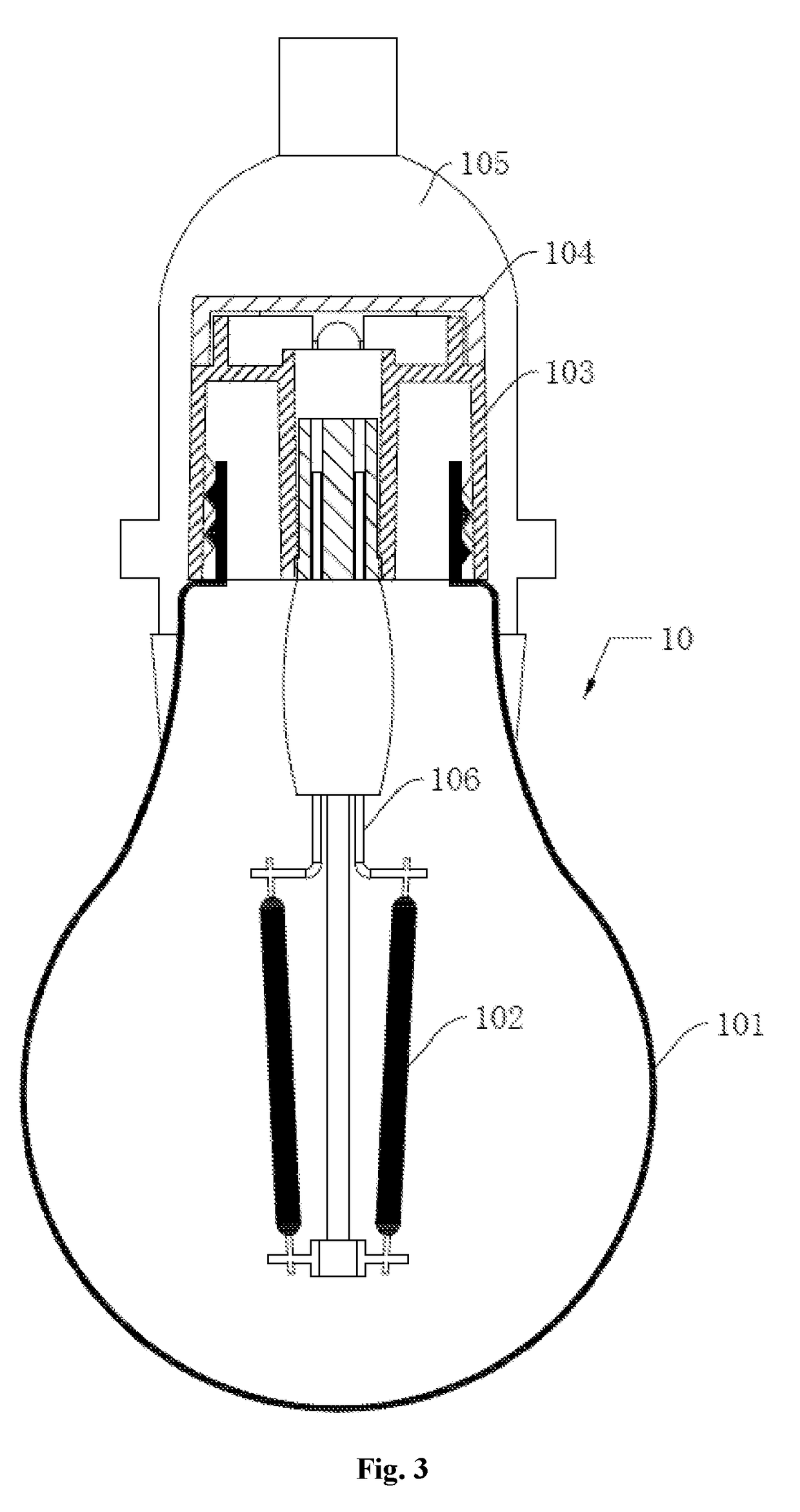
[0049]FIG. 3 shows a sectional structural schematic view of a lighting device 10, and FIG. 4 shows an exploded structural schematic view of the lighting device 10.
[0050]The present example is distinguished from Example 1 in that the lighting device 10 in the present example further includes a bracket 106, the lighting body 102 is embodied as an LED filament, the LED filament is in a column shape, a positive electrode and a negative electrode stretch out from two ends of the LED filament, the LED filament is electrically connected onto the bracket 106, a male connector 1021 is provided on the bracket 106, i.e. the positive electrode and the negative electrode of the LED filament are electrically connected with a positive electrode and a negative electrode of the male connector 1021 respectively.
[0051]The bracket 106 is used to support the lighting body 102 as a carrier of the lighting body 102, so that electrical connection is formed between the lighting body 102 and the lamp base 10...
example 3
[0059]As shown in FIG. 5, the present example provides a lamp string 1, including the lighting device 10 in Example 1 and a lamp wire 20, several lighting devices 10 are electrically connected on the lamp wire 20, and an electrical wire coming out from the lamp base 103 of the lighting device 10 is connected onto the lamp wire 20, thus forming the lamp string 1.
[0060]The lamp wire 20 of the lamp string 1 of the present application is directly electrically connected with the electrical wire coming out from the lamp base 103 of the lighting device 10, without the need of using an adapter on an individual lighting device 10, while the whole lamp string 1 only needs to use one adapter, leading to a lower cost.
[0061]With reference to FIG. 5, the lamp wire 20 of the lamp string 1 of the present example has one end provided with a male connector 210, and the other end provided with a female connector 202 matched with the male connector 201. Through the male connector 201 and the female con...
PUM
| Property | Measurement | Unit |
|---|---|---|
| Flexibility | aaaaa | aaaaa |
Abstract
Description
Claims
Application Information
 - R&D
- Intellectual Property
- Life Sciences
- Materials
- Tech Scout
- Unparalleled Data Quality
- Higher Quality Content
- 60% Fewer Hallucinations
Browse by: Latest US Patents, China's latest patents, Technical Efficacy Thesaurus, Application Domain, Technology Topic, Popular Technical Reports.
© 2025 PatSnap. All rights reserved.Legal|Privacy policy|Modern Slavery Act Transparency Statement|Sitemap|About US| Contact US: help@patsnap.com


