Calibration of a triangulation sensor

a triangulation sensor and sensor technology, applied in the direction of measuring devices, instruments, using optical means, etc., can solve the problems of providing a usable signal over the whole width of the projected laser line, difficult to measure, and low roughness of the surface,

Active Publication Date: 2018-12-27
HEXAGON TECH CENT GMBH
View PDF0 Cites 20 Cited by
  • Summary
  • Abstract
  • Description
  • Claims
  • Application Information

AI Technical Summary

Benefits of technology

[0095]The thermal compensation, i.e. in particular the calibration function, can provide modelling any 6-DOF drift of the laser or the camera independently (i.e. in total 12 degrees of freedom).

Problems solved by technology

However, in case of regions to be illuminated which significantly differ regarding their reflecting properties there still remains the problem of providing a usable signal over the whole width of a projected laser line.
Particularly, surfaces with low roughness, i.e. mirror-like surfaces such as chrome, are difficult to measure due to strong inhomogeneity of the reflected light towards the image sensor.
Another problem with respect to precision of measurements is the possible occurrence of long-term drifts of particular sensor components, e.g. of electronics or optical arrangements, or a drift concerning a relative arrangement of such components.
As one result of such effect position values which are measured with the system may be acquired with particular errors which finally result in erroneous position measurements.
Such tilting or offset can cause significant erroneous measurements for instance regarding calculated distances.
Furthermore, a deviation in position and / or orientation may also occur for the light receiving part of the sensor.
Therefore, there remains a problem of providing reliable measuring values in light of above mentioned long term drifts.
Above described problems relate to external influences on the measuring system which result in possible measurement errors.
Such basic calibration typically is comparatively time consuming with respect to setting up a calibration arrangement and quite complex as there has to be provided exact reference coordinate information.

Method used


Image

  • Calibration of a triangulation sensor
  • Calibration of a triangulation sensor
  • Calibration of a triangulation sensor

Examples


Embodiment Construction

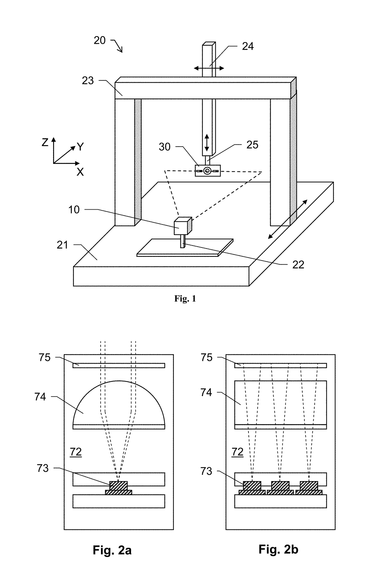
[0124]FIG. 1 shows a calibration embodiment according to the invention. A laser triangulation sensor 10 is arranged on the base 21 of a coordinate measuring machine 20 (CMM). A mounting unit 22 provides a reproducible mounting of such sensor 10 on the CMM 20.

[0125]The CMM 20 further comprises a frame structure having a portal 23 and a Z-ram 24 for providing movability of a probe or tool head 25 relative to the base 21. The head 25 can be moved at least in three axis X, Y, Z. The head and / or the CMM structure may further be designed so that a rotational movement of the head 25 is provided as well.

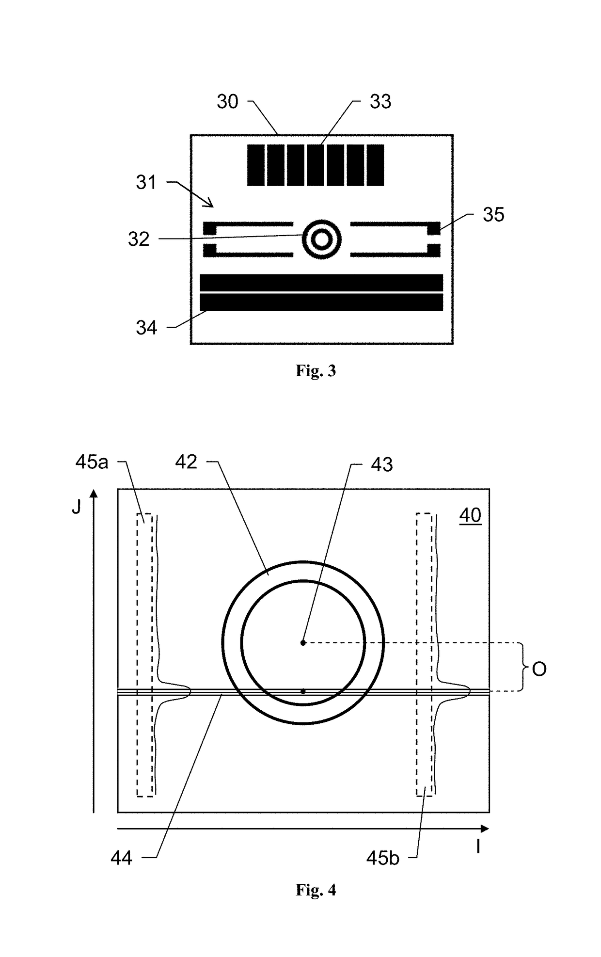
[0126]A calibration target 30 is arranged at the head 25 of the CMM 20. By that, a movement of the target 30 relative to the triangulation sensor 10 can be provided by controlling the CMM 20.

[0127]In general, the CMM 20 and the positioning of the triangulation sensor 10 at a known position on the base 21 provide a defined and known relative positioning of the two calibration elements (sensor...


PUM


Abstract

A method for calibrating a triangulation sensor including a light emitting unit for emitting measuring light and a light receiving unit. The light emitting unit is arranged with known position and orientation relative to the light receiving unit and the triangulation sensor which is adapted to provide triangulation-based position measurements. A calibration setup which comprises the triangulation sensor and a calibration target providing a defined calibration pattern, and a calibration measurement is performed with reference to the calibration target by means of the triangulation sensor. An image of the calibration target is captured by means of the light receiving unit, and the captured image is processed with deriving a pattern image position with reference to the inner sensor image coordinate system and deriving a light image position with reference to the inner sensor image coordinate system.

Description

CROSS-REFERENCE TO RELATED APPLICATIONS[0001]This application claims priority to European Patent Application No. 17177439.1 filed on Jun. 22, 2017. The foregoing patent application are incorporated herein by reference.FIELD OF INVENTION[0002]The present invention generally pertains to respective methods for calibration of a triangulation sensor and for compensation of measurements based on the calibration.BACKGROUND[0003]It is common practice to inspect work pieces subsequent to production e.g. on a coordinate positioning apparatus, such as a coordinate measuring machine (CMM), in order to check for correctness of predefined object parameters, like dimensions and shape of the object. Moreover, a detection of a surface of an unknown object is of interest in many industrial applications. Such measurement typically also may be provided using a coordinate measuring machine or any other suitable type of scanning device.[0004]In a conventional 3-D coordinate measurement machine, a probe h...

Claims


Application Information

Patent Timeline
Patent Type & Authority Applications(United States)
IPC IPC(8): G01B11/00
CPCG01B11/005G01B11/2518G01B5/0014G01B11/2504G01B21/042
Inventor STIGWALL, JOHANAEBISCHER, BEATCHAMP, PETER
Owner HEXAGON TECH CENT GMBH
Why Eureka
Try Eureka