Illuminator for a wearable display

a technology of illuminator and wearable display, which is applied in the direction of instruments, polarising elements, optical light guides, etc., to achieve the effects of reducing the size of illuminator, increasing the incoming light angle, and reducing the distance between the condenser lens

Active Publication Date: 2018-12-27
ISHII FUSAO MR +1
View PDF4 Cites 22 Cited by
  • Summary
  • Abstract
  • Description
  • Claims
  • Application Information

AI Technical Summary

Benefits of technology

[0009]Another example of this invention is to reduce the size of illuminator using additional ¼λ retarder which rotates the angle of polarization of light by 90 degrees placed on the a opposite face to a display device as shown in FIG. 10. This configuration reduces the distance between a condenser lens and a display device which helps to increase the incoming light angle. Combined with a homogenizer, an example is shown at FIG. 11.

Problems solved by technology

But in case of see-through displays such as eyeglass displays and head-up displays, there is no physical screen exists and an image can be seen only in so called “Eyebox” wherein a viewer can see an image and often tends to be very small.

Method used


Image

  • Illuminator for a wearable display
  • Illuminator for a wearable display
  • Illuminator for a wearable display

Examples


Embodiment Construction

[0024]The detail descriptions of various embodiments below illustrate various illuminators to provide light beams to display device of a see-though display system having wide angle (large NA) enough to ensure a large eyebox for a viewer.

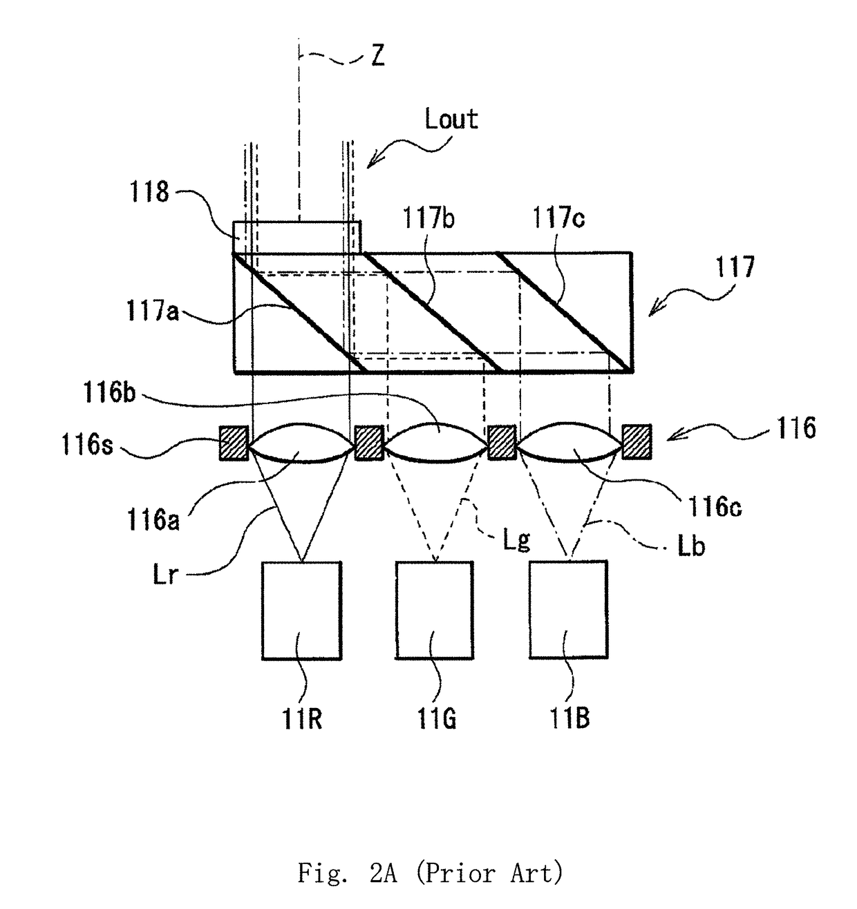
[0025]FIG. 6 and FIG. 7 show an exemplary embodiment of this invention wherein a micro-lens-array (1002) collimates multiple light sources (1001) to a set of dichroic mirrors (1005) to combine light beams into a single beam. The single beam is expanded by an expander lens (1006) and lead to a collimation lens (1007). The collimated beam is divided into multiple beams by a second micro-lens-array (1008) and focused on a third micro-lens-array (1009) where the image is conjugate with the light source. A condenser lens (1010) is placed next to the third micro-lens-array (1009) and light beams are passed to a prism (1011) and reflected toward a polarized beam splitter PBS (1012) by the prism (1011). The reflected light is focused on the display device (1...


PUM


Abstract

A compact illuminator for a see-through image display system with highly uniform light distribution is disclosed. This invention enables wearable displays such as eye-glass type see-through display. This system provides a wide divergent beam from a display device so that a viewer can have a large eyebox.

Description

CROSS REFERENCE TO RELATED APPLICATIONS[0001]This application is a Non-Provisional Application that claims the benefits of a previously filed Provisional Application 62 / 493,077 filed on Jun. 21, 2016. This Application is also a Continuation in Part (CIP) of Patent Application PCT / US2014 / / 000153 filed on Jun. 23, 2014, which is a Non-Provisional Application of a Provisional Application 61 / 957,258 filed on Jun. 27, 2013.TECHNICAL FIELD[0002]This invention relates to an illumination system for a wearable display system for projecting an image to a diffractive optical element enabling a see-through display with high resolution and wide field of view. More particularly, this invention relates to a very compact illuminator suitable for wearable displays with very small form factor.BACKGROUND ART[0003]Wearable displays have received broad attention in recent years after smart phones became popular and are well accepted by the market. Wearable displays provide the benefits of hands free op...

Claims


Application Information

Patent Timeline
Patent Type & Authority Applications(United States)
IPC IPC(8): F21V8/00G02B27/01
CPCG02B6/0031G02B27/0172G02B2027/0174G02B2027/0123G02B2027/0178G02B5/30G02B2027/0138G02B2027/012G02B2027/011G02B27/48G02B27/0905G02B27/0961G02B27/141G02B27/283
Inventor ISHII, FUSAOABURAKAWA, YUJITAKAHASHI, KAZUHIKOMURAKAMI, KEIICHINAKANISHI, MIKIKO
Owner ISHII FUSAO MR
Why Eureka
Try Eureka