
Systems and methods to harvest energy and determine water holdup using the magnetohydrodynamic principle

a technology of magnetohydrodynamo and energy harvesting, applied in the direction of dynamo-electric machines, home appliance efficiency improvement, sustainable buildings, etc., can solve the problems of wire damage and unsatisfactory powering of these devices through wires, and achieve the effect of reducing fluid flow and more power

Active Publication Date: 2018-12-27
SAUDI ARABIAN OIL CO
View PDF3 Cites 4 Cited by
  • Summary
  • Abstract
  • Description
  • Claims
  • Application Information

AI Technical Summary

Benefits of technology

The MHD power generation system is designed to withstand high temperatures without degradation. It uses materials that can handle high temperatures. In addition, the system has one or more electric valves that are choked to decrease the flow of non-conductive fluid and optimize the flow of conductive fluid. This results in more power generation.

Problems solved by technology

Further, for efficiency reasons, powering these devices through wires is not desirable given the fact that remote power locations can be costly to operate.
Given the length of pipeline systems, wires are likely to be damaged.

Method used


Image

  • Systems and methods to harvest energy and determine water holdup using the magnetohydrodynamic principle
  • Systems and methods to harvest energy and determine water holdup using the magnetohydrodynamic principle
  • Systems and methods to harvest energy and determine water holdup using the magnetohydrodynamic principle

Examples


Embodiment Construction

[0027]Advantages and features of the systems and methods of accomplishing the same will be apparent by referring to embodiments described below in detail in connection with the accompanying drawings. However, the systems and methods are not limited to the embodiments disclosed below and may be implemented in various different forms. The embodiments are provided only for completing the disclosure and for fully representing the scope of the disclosed technology to those skilled in the art.

[0028]For simplicity and clarity of illustration, the drawing figures illustrate the general manner of construction, and descriptions and details of well-known features and techniques may be omitted to avoid unnecessarily obscuring the discussion of the described embodiments of the invention. Additionally, elements in the drawing figures are not necessarily drawn to scale. For example, the dimensions of some of the elements in the figures may be exaggerated relative to other elements to help improve ...


PUM


Abstract

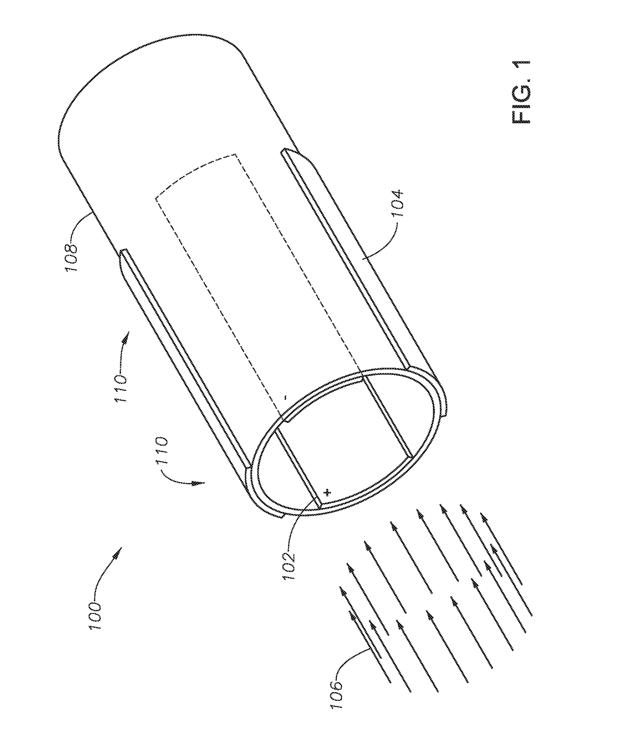
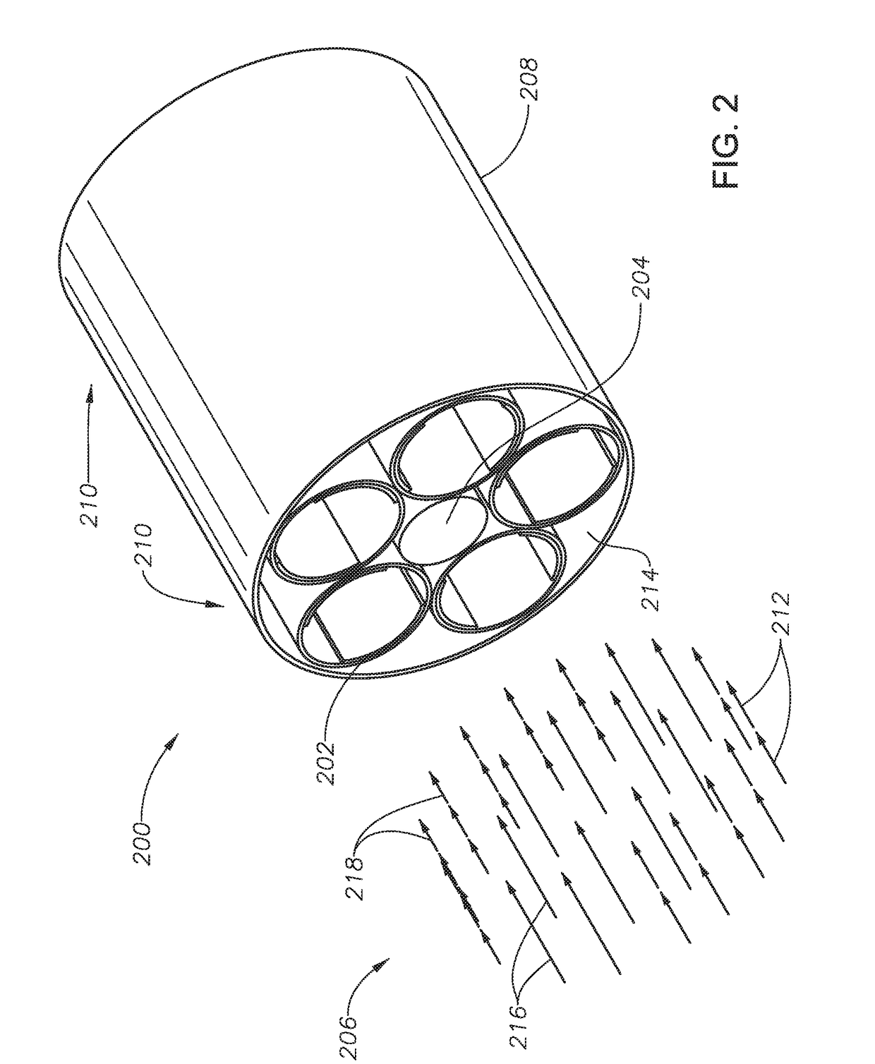
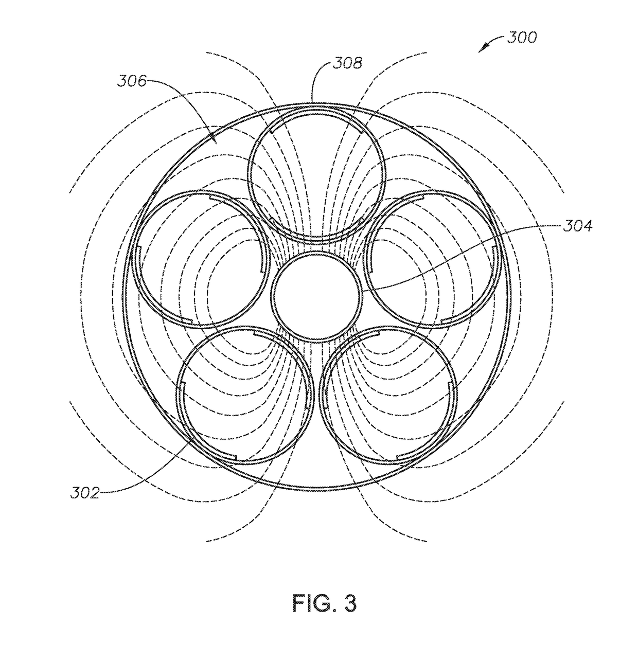
Embodiments provide systems and methods for creating and storing energy using the magnetohydrodynamic principle and the flow of a conductive fluid through a magnetic field downhole in a pipeline system. The system can also be configured to determine water holdup using the magnetohydrodynamic principle. The energy the system generates can be used to control electric valves and other electronic devices along the pipeline. The power storing and generating system can be configured to include permanent magnets, electrode pairs, isolation material, and a conductive flowing multiphase media. The multiphase media, i.e., oil, gas, water, or a mixture, flows through a pipeline that has electrodes in direct contact with the media and magnets also configured adjacent the media. The electrode pairs can be arranged inside of the pipeline opposite each other, with a permanent magnet placed between the electrodes and flush to the inside of the pipe, with flux lines perpendicular to the flow direction. Power output from the system is a function of the conductive fluid volume, flow velocity, magnet strength, and electrode size. Various embodiments include different arrangements of permanent magnets and electrode pairs.

Description

BACKGROUNDField[0001]Embodiments of the present disclosure relate to systems and methods for generating electrical power using the magnetohydrodynamic (“MHD”) principle. More particularly, embodiments relate to utilizing multiphase flow to determine water holdup and to create and store energy to power downhole equipment in a pipeline system.Description of Related Art[0002]The oil and gas industry has a fairly large need for electrical power in all areas of its business, including wells, pipelines, and refineries. Various equipment used in the oil and gas industry, such as valves and sensors require power to function. This power can be supplied by a power grid or other means. However, it is also desirable to power these devices through the use of power generated on site. Further, for efficiency reasons, powering these devices through wires is not desirable given the fact that remote power locations can be costly to operate. Given the length of pipeline systems, wires are likely to be...

Claims


Application Information

Patent Timeline
Patent Type & Authority Applications(United States)
IPC IPC(8): H02K44/12E21B34/06H02K44/08H02K44/10
CPCH02K44/12H02K44/10H02K44/085E21B34/066H02K44/08H02J7/32H02J50/001H02J50/00Y02B40/00
Inventor HVEDING, FRODEARSALAN, MUHAMMAD
Owner SAUDI ARABIAN OIL CO
Learn More