
Systems and method for advanced additive manufacturing

a technology of additive manufacturing and systems, applied in the field of additive manufacturing, can solve the problems of poor surface finish of the overhang or downward facing surface, affecting the quality of components, and local overheating,

Active Publication Date: 2019-01-03
GENERAL ELECTRIC CO
View PDF5 Cites 23 Cited by
  • Summary
  • Abstract
  • Description
  • Claims
  • Application Information

AI Technical Summary

Benefits of technology

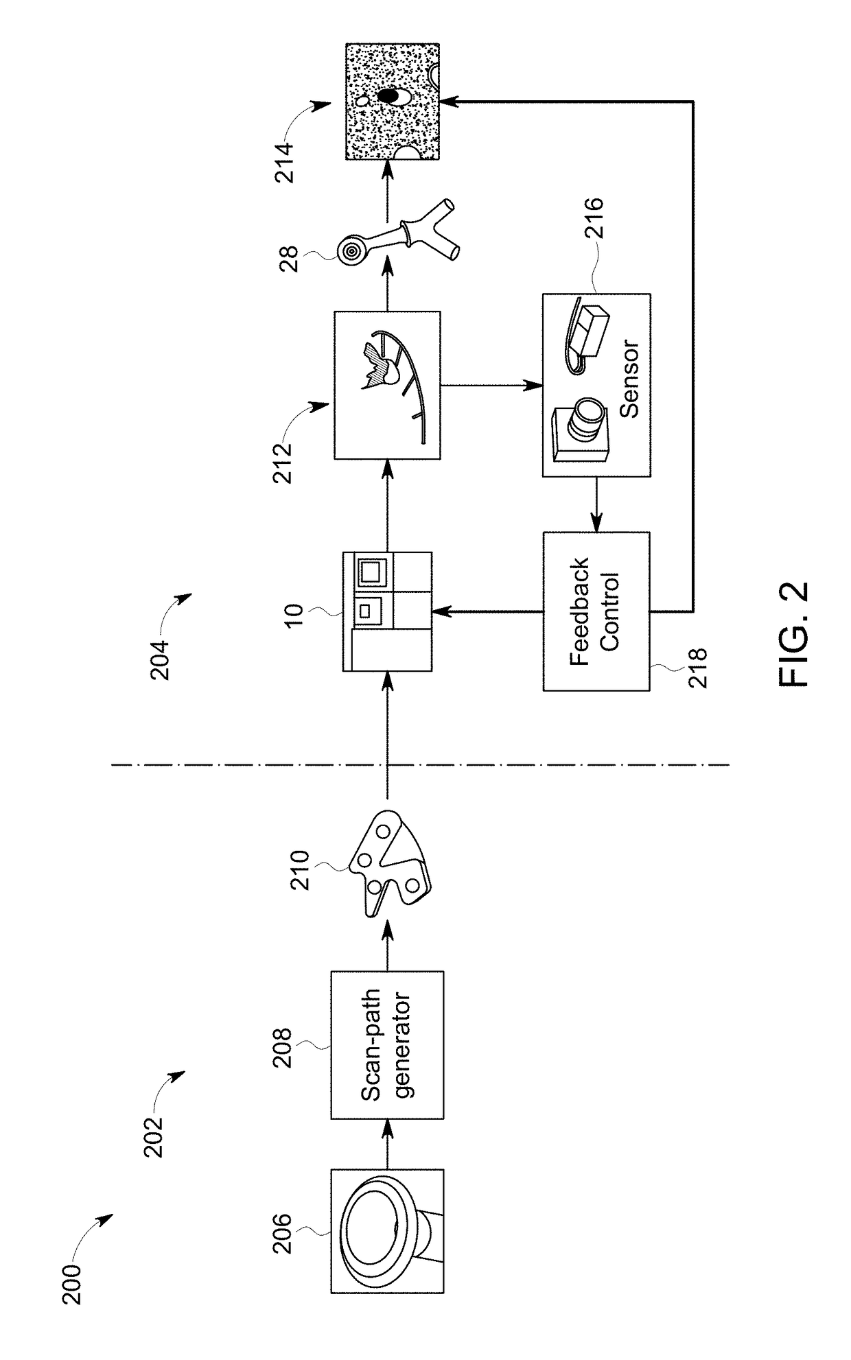
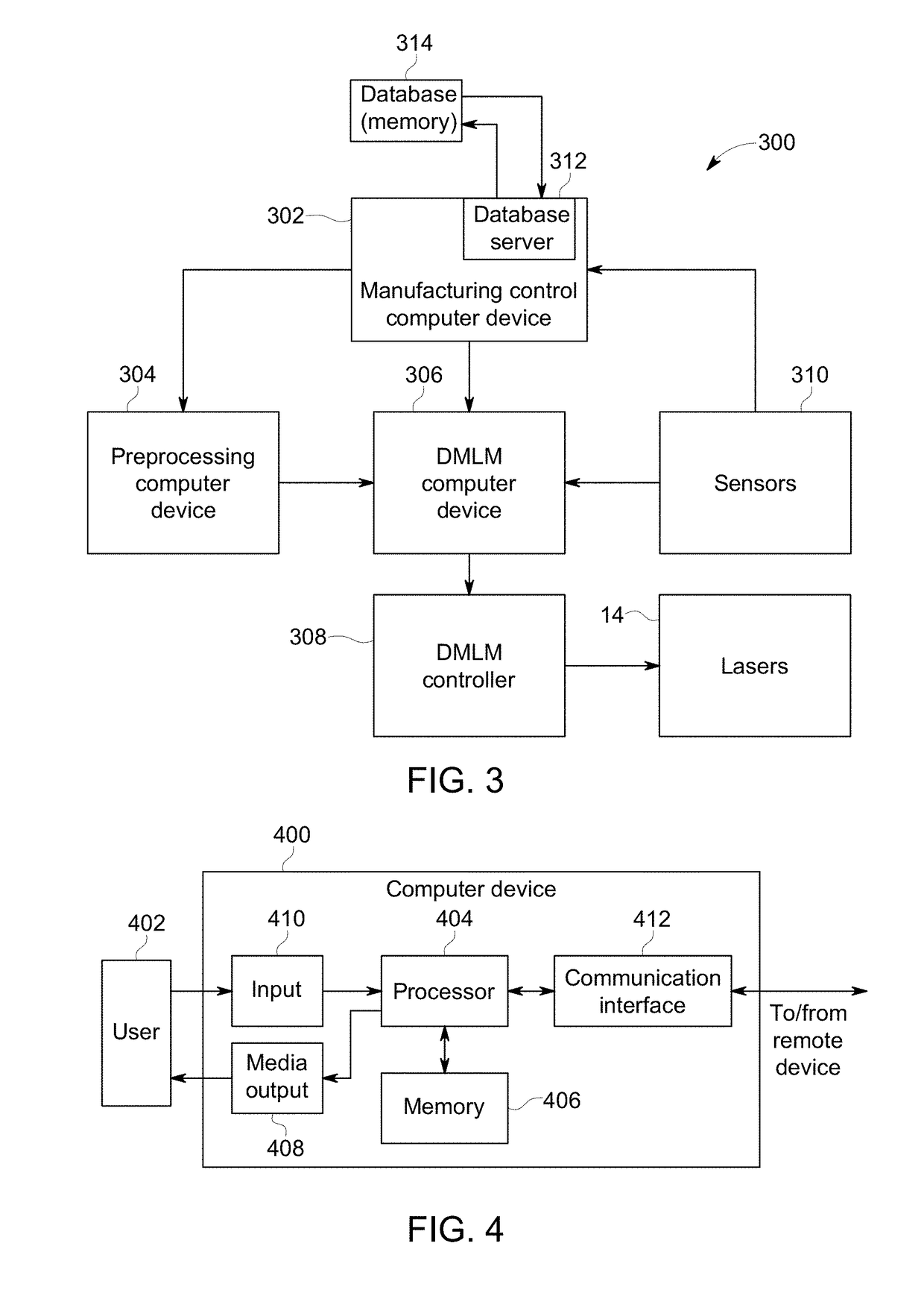
The patent describes a manufacturing computer device that can adapt the additive manufacturing process of a part based on sensor information from the build. The device receives a build file with multiple geometries and their corresponding build parameters. It compares the sensor information to the build parameters and identifies any differences. It then automatically adjusts the build parameters for the subsequent geometries based on the differences, and sends the updated build file to the additive manufacturing machine for the part. This allows for real-time adaptive manufacturing and improves the quality of the part.

Problems solved by technology

In some known DMLM systems, component quality may be impacted by excess heat and / or variation in heat being transferred to the metal powder by the laser device within the melt pool.
As a result, local overheating may occur, particularly at the overhanging surfaces.
The melt pool produced by the laser device may become too large resulting in the melted metal spreading into the surrounding powdered metal as well as the melt pool penetrating deeper into the powder bed, pulling in additional powder into the melt pool.
The increased melt pool size and depth, and the flow of molten metal may generally result in a poor surface finish of the overhang or downward facing surface.
Other issues with variations in the material and the application of the material may also occur during manufacturing based on a plurality of factors, which may lead to the object being unusable.

Method used


Image

  • Systems and method for advanced additive manufacturing
  • Systems and method for advanced additive manufacturing
  • Systems and method for advanced additive manufacturing

Examples


Embodiment Construction

[0028]In the following specification and the claims, reference will be made to a number of terms, which shall be defined to have the following meanings.

[0029]The singular forms “a”, “an”, and “the” include plural references unless the context clearly dictates otherwise.

[0030]“Optional” or “optionally” means that the subsequently described event or circumstance may or may not occur, and that the description includes instances where the event occurs and instances where it does not.

[0031]Approximating language, as used herein throughout the specification and claims, may be applied to modify any quantitative representation that could permissibly vary without resulting in a change in the basic function to which it is related. Accordingly, a value modified by a term or terms, such as “about”, “approximately”, and “substantially”, are not to be limited to the precise value specified. In at least some instances, the approximating language may correspond to the precision of an instrument for...


PUM

PropertyMeasurementUnit
wavelengthaaaaaaaaaa
wavelengthsaaaaaaaaaa

Abstract

A manufacturing computer device for dynamically adapting additive manufacturing of a part is provided. The manufacturing computer device includes at least one processor in communication with at least one memory device. The at least one memory device stores a build file for building the part including a plurality of geometries that each include one or more values of a first build parameter. The processor is programmed to receive sensor information of a build of the part by a machine, compare the sensor information for each geometry of the plurality of geometries to the corresponding one or more values of the first build parameter, determine one or more values for a second build parameter for each of the geometries based on the one or more differences, and generate an updated build file for the part including the one or more values for the second build parameter.

Description

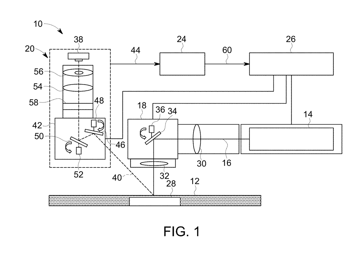
BACKGROUND[0001]The field of the disclosure relates generally to additive manufacturing and, more particularly, to systems and method for dynamically adapting additive manufacturing of a part, build or both.[0002]Many additive manufacturing systems (also known as three dimensional (3D) printers) generate three-dimensional objects through a layer-by-layer process. The system generates an object through placing successive layers of a material based on computer control. At least some additive manufacturing systems involve the buildup of a powdered material to make a component. This method can produce complex components from expensive materials at a reduced cost and with improved manufacturing efficiency. At least some known additive manufacturing systems, such as Direct Metal Laser Melting (DMLM) systems, fabricate components using a laser device and a powder material, such as, without limitation, a powdered metal. The laser device generates a laser beam that melts the powder material ...

Claims


Application Information

Patent Timeline
Patent Type & Authority Applications(United States)
IPC IPC(8): G01N35/10B22F3/105B33Y50/02G06F19/00
CPCG01N35/1011B22F3/1055B33Y50/02B22F2003/1057B33Y10/00B33Y30/00G06F19/00B33Y50/00B29C64/386B22F12/41B22F12/90B22F12/44B22F12/49B22F10/368B22F10/25B22F10/80B22F10/28Y02P10/25G05B19/4099G05B2219/49007
Inventor BLOM, ROGIER SEBASTIAANFREER, JOHNROBINSON, DEAN MICHAELROYCHOWDHURY, SUBHRAJITMATHEWS, JR., HARRY KIRK
Owner GENERAL ELECTRIC CO
Learn More