Image guided radiation therapy system

a radiation therapy system and image technology, applied in the field of image guided radiation therapy system, can solve the problems of inability to complete real-time, inability to process the ct dataset in real time to generate a bev image, and inability to achieve the effect of real-time completion,

Active Publication Date: 2019-01-03
ALBERTA HEALTH SERVICES
View PDF3 Cites 8 Cited by
  • Summary
  • Abstract
  • Description
  • Claims
  • Application Information

AI Technical Summary

Benefits of technology

[0015]FIG. 6 is a schematic view of a radiation beam used to target patient tissue based on images encoded from a magnetic field produced by a conventional gradient coil configuration;
[0016]FIG. 7 is a schematic view of the magnetic field produced by a conventional gradient coil configuration;

Problems solved by technology

However, processing the CT dataset in real time to generate a BEV image is computationally intensive and cannot be completed in real-time.
Thus, targeting the radiation source based on this conventionally obtained image may lead to a decreased radiation dose at the target than what was planned and / or unnecessary dose to tissue surrounding the target.
For example, a 5 cm thick image slice may result in up to 4 mm of targeting error, 15 cm from the central beam axis, assuming a 100 cm distance from the radiation source.
While it may be possible to process the image data collected in MRI by ray tracing to produce an BEV image, similar to the methodology described above for CT, this processing is performed after the data is captured and therefore not available in real-time.
Furthermore, the 3D image data collected in MRI requires significantly more data acquisition in general than does the image data collected in CT.
As a result, significant time is required to produce a BEV image.

Method used


Image

  • Image guided radiation therapy system
  • Image guided radiation therapy system
  • Image guided radiation therapy system

Examples


Embodiment Construction

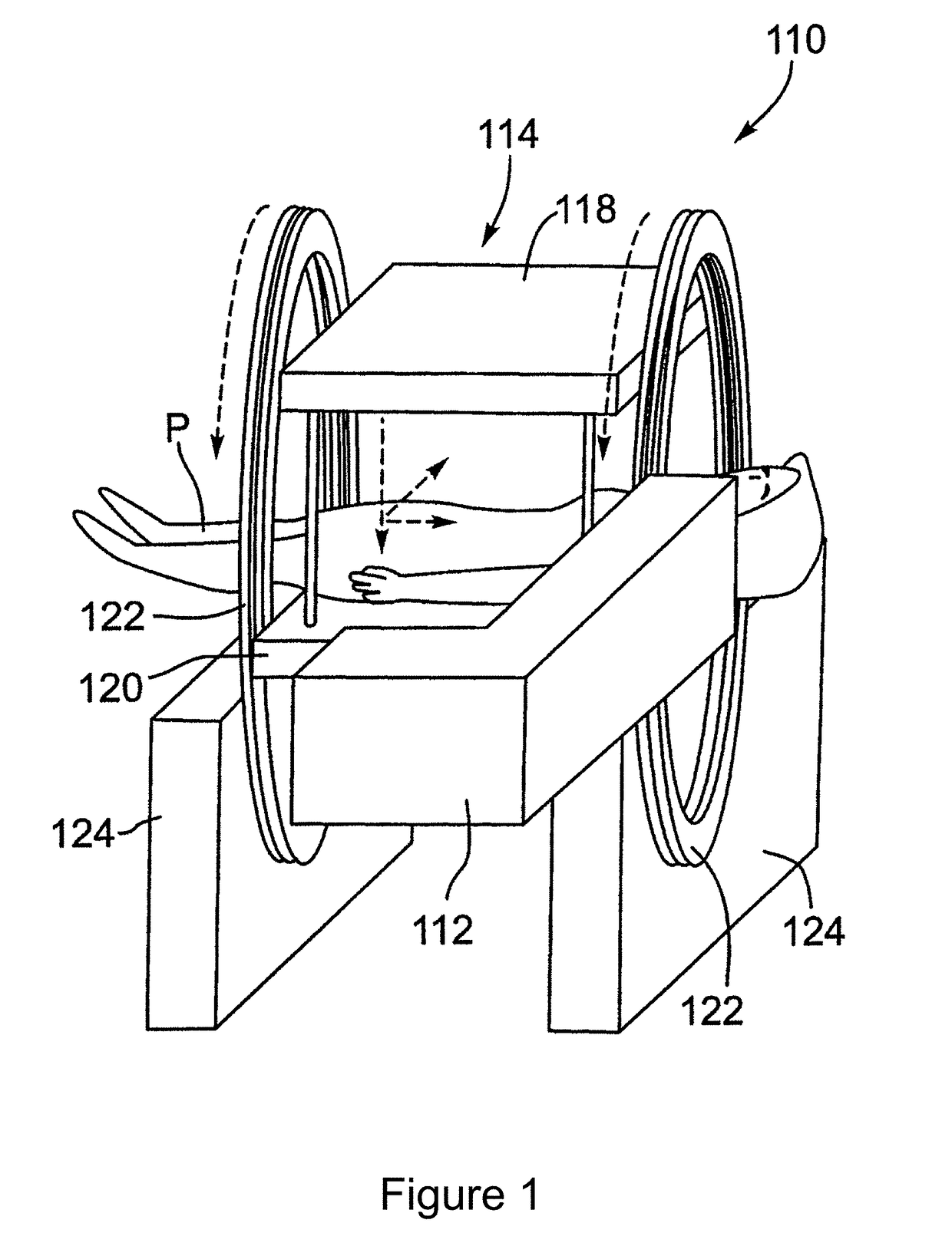
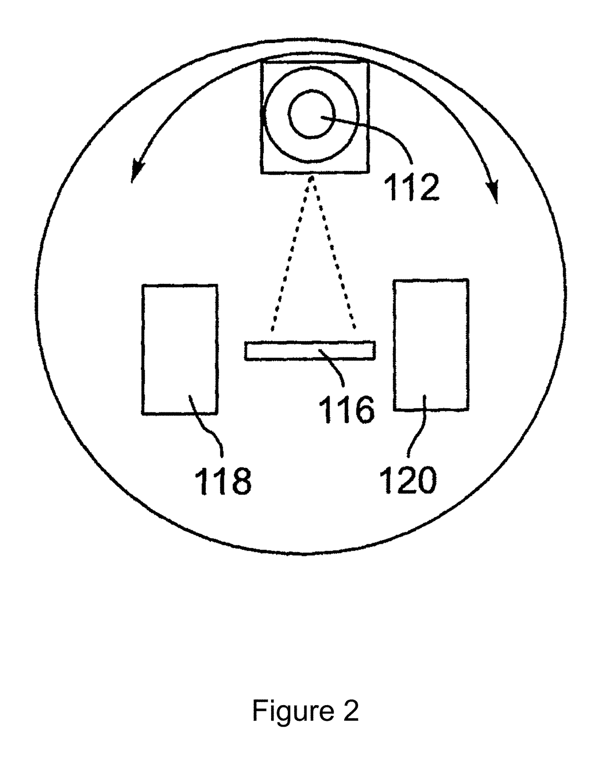
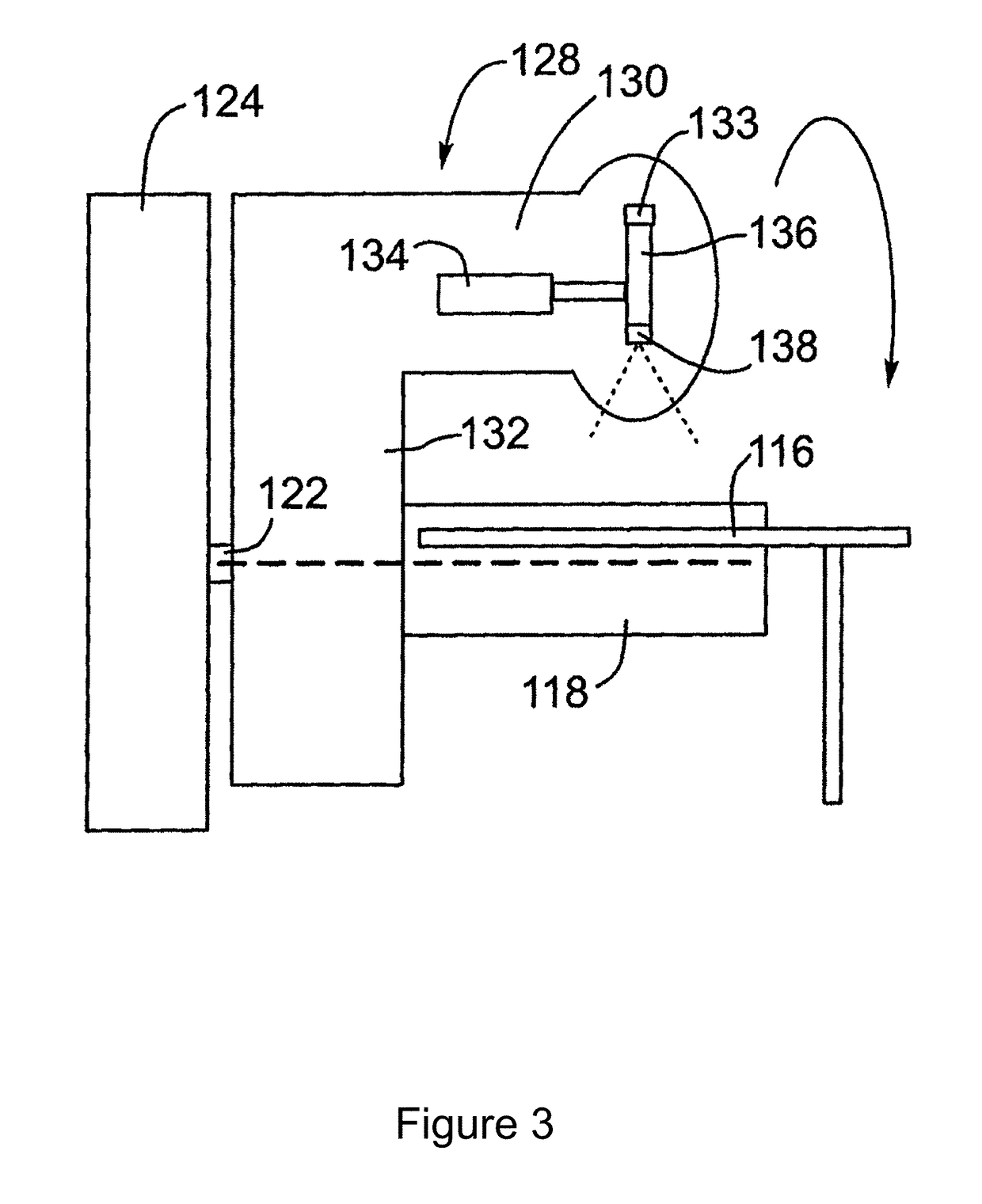
[0022]For convenience, like numerals in the description refer to like structures in the drawings. Referring to FIGS. 1 to 3, an integrated radiation source and MRI system is shown and is generally identified by reference numeral 110. As can be seen, the integrated radiation source and MRI system 110 includes a radiation source and an MRI apparatus 114. In this embodiment, the radiation source is a linear accelerator or linac 112. As will be described, the linac 112 is configured to generate a treatment beam. The MRI apparatus 114 is configured to image a patient in real-time. The linac 112 and the MRI apparatus 114 are coupled to a rotatable gantry 122 so that they can be rotated in unison to treat a patient P.

[0023]In this particular example, the MRI apparatus 114 comprises a biplanar magnet having a pair of opposing magnet poles 118 and 120 creating a 0.2 T magnetic field strength. The MRI apparatus 114 is an open bore type including a table 116 on which the patient P can lay. In ...


PUM


Abstract

A magnetic resonance (MR)-radiotherapy (RT) hybrid system for treating a patient is disclosed. The MR-RT hybrid system includes a radiation source for supplying a radiation beam to treat the patient and an MR imaging (MRI) apparatus for generating a divergent gradient field shaped to match a divergent geometry of the radiation beam of the radiation source.

Description

[0001]The present invention relates generally to magnetic resonance guided radiotherapy treatment systems and, specifically, to an apparatus and method for magnetic resonance guided radiotherapy treatment with beam's eye view imaging.BACKGROUND[0002]Image guided radiotherapy (IGRT) has become the state of the art in radiation treatment. IGRT may utilize two-dimensional (2D) projection images or three-dimensional (3D) cone beam computed tomography (CT) images that are acquired prior to treatment. These images are compared to a set of pre-treatment images to ensure the patient has been set up accurately and consistently each treatment session. While CT, for example reconstructs in a standard cartesian geometry, the geometry of the radiation treatment beam originates from a divergent source. Beam's eye view (BEV) projection is commonly used to visualize patient anatomy to determine exactly what tissue will be irradiated from the divergent treatment beam.[0003]In BEV projection, the 3D ...

Claims


Application Information

Patent Timeline
Patent Type & Authority Applications(United States)
IPC IPC(8): G01R33/48G01R33/38A61N5/10A61B5/055
CPCG01R33/4808A61B5/055A61N5/1077G01R33/3806G01R33/4812A61N5/1049A61N2005/1055
Inventor WACHOWICZ, KEITHFALLONE, B. GINOMURRAY, BRAD
Owner ALBERTA HEALTH SERVICES
Why Eureka
Try Eureka