Impeller of centrifugal fan and method and apparatus for manufacturing the same

Active Publication Date: 2019-01-10
DAIKIN IND LTD
View PDF14 Cites 20 Cited by
  • Summary
  • Abstract
  • Description
  • Claims
  • Application Information

AI Technical Summary

Benefits of technology

[0070]To inexpensively manufacture the impeller of the centrifugal fan by welding between the multiple blades arranged annularly around the rotational axis and the main plate and the shroud arranged opposite to two blade axial ends that are both ends of each of the blades in the direction of the rotational axis, it is necessary to reduce molds to be used and molding processes for forming, in advance, edges, through-holes, and protrusions that are required for welding, make smaller the areas of welded portions, and downsize ultrasonic horns and an ultrasonic oscillator to be included.
[0071]In this aspect, as described above, the main plate-side ultrasonic horn, which gives the ultrasonic vibration to the blades and the main plate to weld between the main plate-side blade axial ends and the main plate, includes the main plate-side insertion portions that are inserted through the main plate to the portions of the main plate-side blade axial ends. In addition, the shroud-side ultrasonic horn, which gives the ultrasonic vibration to the blades and the shroud to weld between the shroud-side blade axial ends and the shroud, includes the shroud-side insertion portions that are inserted through the shroud to the portions of the shroud-side blade axial ends. The main plate-side ultrasonic horn having the main plate-side insertion portions gives the ultrasonic vibration to the blades and the main plate, melts the main plate-side blade axial ends and the

Problems solved by technology

In the ultrasonic welding methods described in Patent Documents 1 and 2, however, since it is necessary to form the edges, the through-holes, and the protrusions on the portions serving as the main plate-side welded portions and the shroud-side welded portions in advance, the molds and molding processes for forming these portions cause an increase in the cost, and the areas of the main plate-side welded portions and the areas of the shroud-side welded portions are also increased.
With the areas of the main plate-side welded portions and the areas of the shroud-side welded portions being increased, an ultrasonic horn and an ultrasonic oscillator that give ultrasonic vibration are increased in size, resulting in

Method used


Image

  • Impeller of centrifugal fan and method and apparatus for manufacturing the same
  • Impeller of centrifugal fan and method and apparatus for manufacturing the same
  • Impeller of centrifugal fan and method and apparatus for manufacturing the same

Examples


Example

[0110]Hereinafter, an embodiment of an impeller of a centrifugal fan and a method and apparatus for manufacturing the impeller pertaining to the present invention is described with reference to the accompanying drawings. Note that specific configurations described in the embodiment of the impeller of the centrifugal fan and the method and apparatus for manufacturing the impeller pertaining to the present invention are not limited to the following embodiment and its modified examples, and may be changed within the gist of the present invention.

(1) Entire Configuration of Air Conditioner

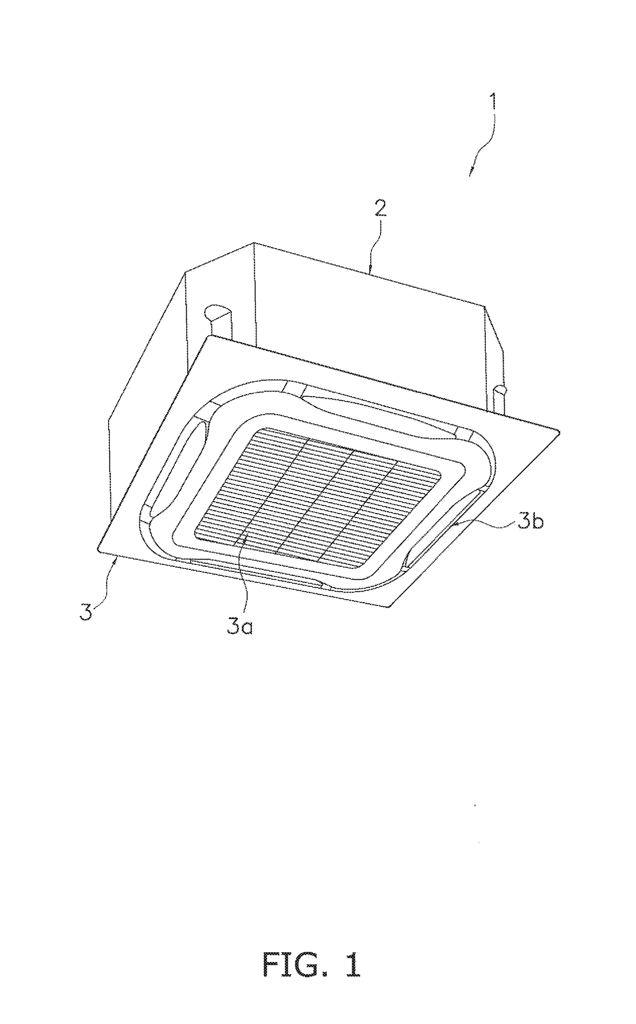
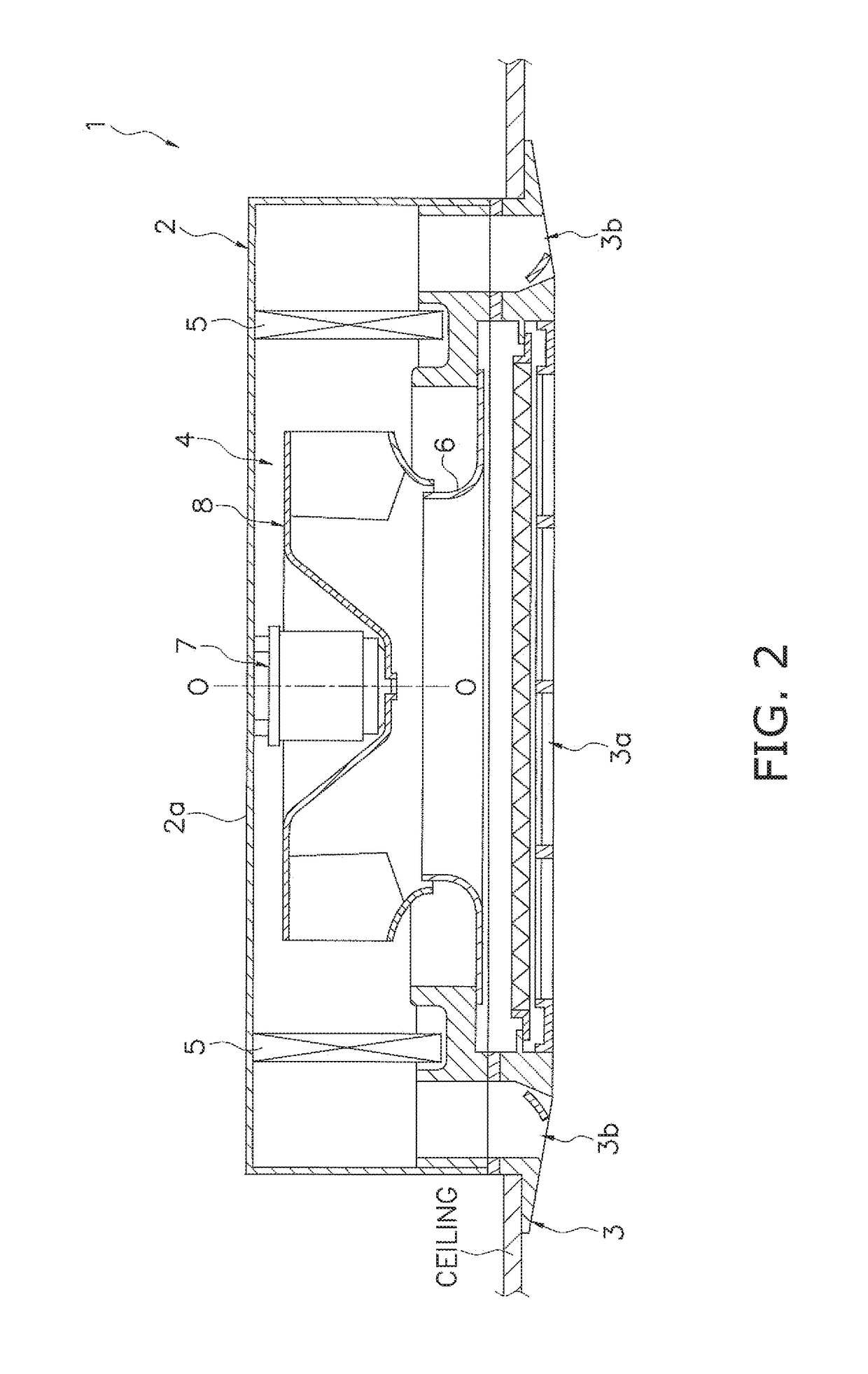
[0111]FIG. 1 is a perspective view (omitting a ceiling) of an air conditioner 1 in which a centrifugal fan 4 having an impeller 8 according to the embodiment of the present invention is used. The air conditioner 1 is a ceiling-mounted air conditioner and mainly includes a casing 2 storing various constituent devices therein and a laminate panel 3 installed on the lower side of the casing 2.

[0112]The ca...


PUM

PropertyMeasurementUnit
Timeaaaaaaaaaa

Abstract

An impeller of a centrifugal fan includes multiple blades arranged annularly around a rotational axis, a main plate, a shroud, main plate-side welded portions between main plate-side blade axial ends of the blades and the main plate, and shroud-side welded portions between shroud-side blade axial ends of the blades and the shroud. The main plate is arranged opposite to main plate-side blade axial ends. The shroud is arranged opposite to shroud-side blade axial ends. The main plate-side welded portions have main plate-side welding holes that are recesses extending through the main plate to portions of the main plate-side blade axial ends. The shroud-side welded portions have shroud-side welding holes that are recesses extending through the shroud to portions of the shroud-side blade axial ends.

Description

TECHNICAL FIELD[0001]The present invention relates to an impeller of a centrifugal fan, and a method and apparatus for manufacturing the impeller of the centrifugal fan, and more particularly to an impeller of a centrifugal fan, and a method and apparatus for manufacturing the impeller of the centrifugal fan, where the impeller being manufactured by welding between multiple blades arranged annularly around a rotational axis and a main plate and a shroud, the main plate and the shroud being respectively arranged opposite to two blade axial ends that are both ends of each of the blades in the direction of the rotational axis.BACKGROUND ART[0002]In an air conditioner, an air cleaner, or the like, a centrifugal fan is used to suck, supply, and discharge air in some cases. An impeller that constitutes the centrifugal fan mainly includes: multiple blades arranged annularly around a rotational axis, and a main plate and a shroud arranged opposite to two blade axial ends that are both ends ...

Claims


Application Information

Patent Timeline
IPC IPC(8): F04D29/66F04D29/28F04D29/30F04D29/62B23K20/10
CPCF04D29/666F04D29/281B23K20/106F04D29/624F04D29/30B06B1/02B23K20/10F04D29/28F04D29/62B29C65/08F04D29/282B29C66/21B29C66/81429B29C66/81433B29C66/8322B29C66/8432B29L2031/08B29C66/65B29C66/81463B29C66/73921B29C66/543B29C65/7814F04D29/023F04D29/626B29C66/54
Inventor KUMAOU, SHIGEO
Owner DAIKIN IND LTD
Why Eureka
Try Eureka