Fuel supply device

a technology of fuel supply and nozzle, which is applied in the direction of fuel injection apparatus, charge feed system, electric control, etc., can solve the problems of unsatisfactory cover body breakage, fuel vapor may leak from the fuel tank, and possible cover body breakage, etc., to reduce section modulus or cross-sectional area , the effect of reducing the cross-sectional area

Active Publication Date: 2019-01-17
AISAN IND CO LTD
View PDF0 Cites 7 Cited by
  • Summary
  • Abstract
  • Description
  • Claims
  • Application Information

AI Technical Summary

Benefits of technology

[0025]At the coupling stay of the second aspect, the lower stay, which is installed to the pump unit, is slidably fitted to the upper stay in the top-to-bottom direction while the upper stay extends on the lower side of the cover body. According to the second aspect, in which the stress concentrating portion is formed at the specific location of the lower stay, when an excessive load is exerted along the coupling stay in response to excessive expansion and contraction of the fuel tank, the stress concentrating portion, which reduces the cross-sectional area to concentrate the stress around the stress concentrating portion, is broken first with higher priority over the cover body. Therefore, due to the prioritized breakage of the lower stay, which is farther spaced from the cover body in comparison to the upper stay, it is possible to limit a breakage of the cover body that would result in fuel vapor leakage from the fuel tank.
[0026]The stress concentrating portion according to a third aspect of the present disclosure is formed at the specific location that is located immediately above a lower end part of the lower stay that receives a load from the bottom wall. According to the third aspect, when the fuel tank is excessively expanded and contracted, the stress tends to concentrate at the stress concentrating portion, at which the section modulus or the cross-sectional area is reduced, at the specific location of the lower stay, which is placed immediately above the lower end part that receives the excessive load from the bottom wall of the fuel tank. Accordingly, the breakage of the lower stay, which is prioritized over the cover body, can be reliably induced, so that a damage limiting effect for limiting the damage of the cover body can be increased.

Problems solved by technology

Therefore, when the expansion and contraction of the fuel tank become excessive, an excessive load is exerted along the coupling stay to the cover body, and thereby breakage of the cover body may possibly occur.
In a case where the cover body is broken, fuel vapor may leak from the fuel tank.
Therefore, the breakage of the cover body is not desirable.

Method used


Image

  • Fuel supply device
  • Fuel supply device
  • Fuel supply device

Examples


first embodiment

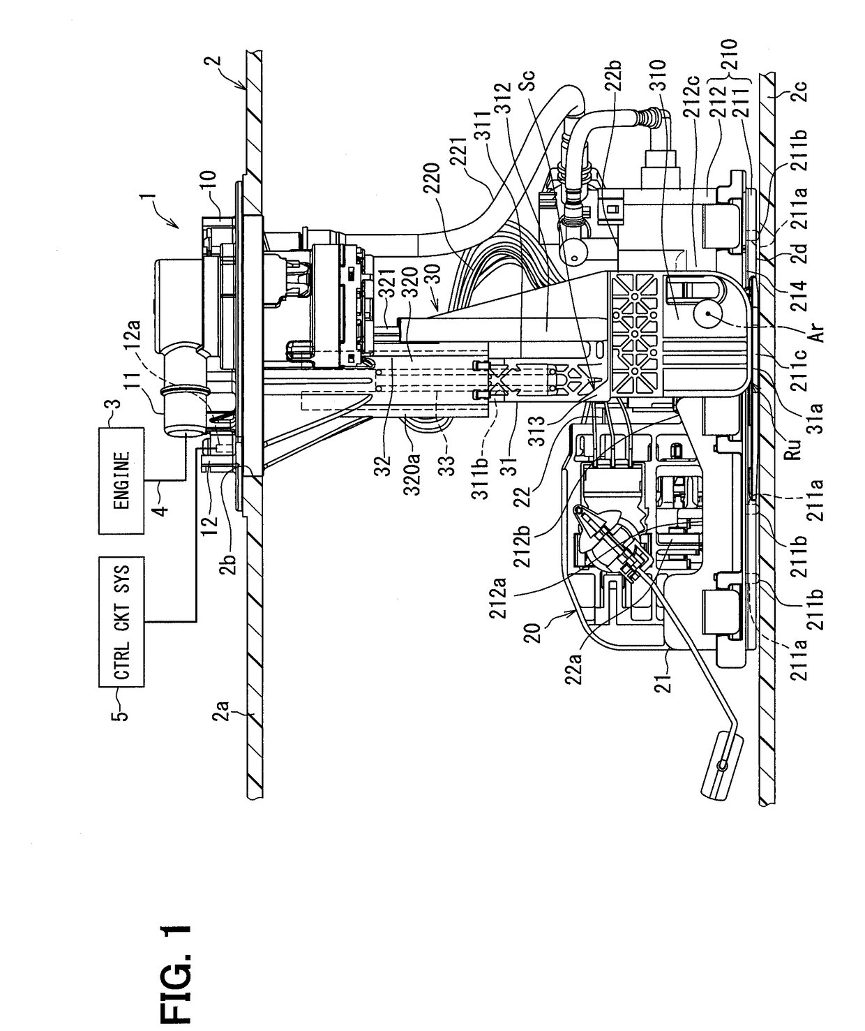
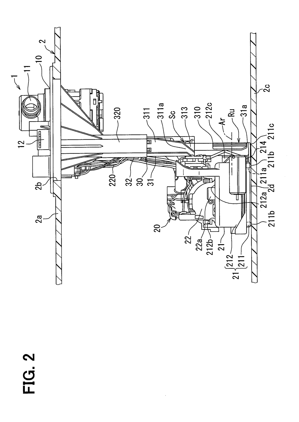
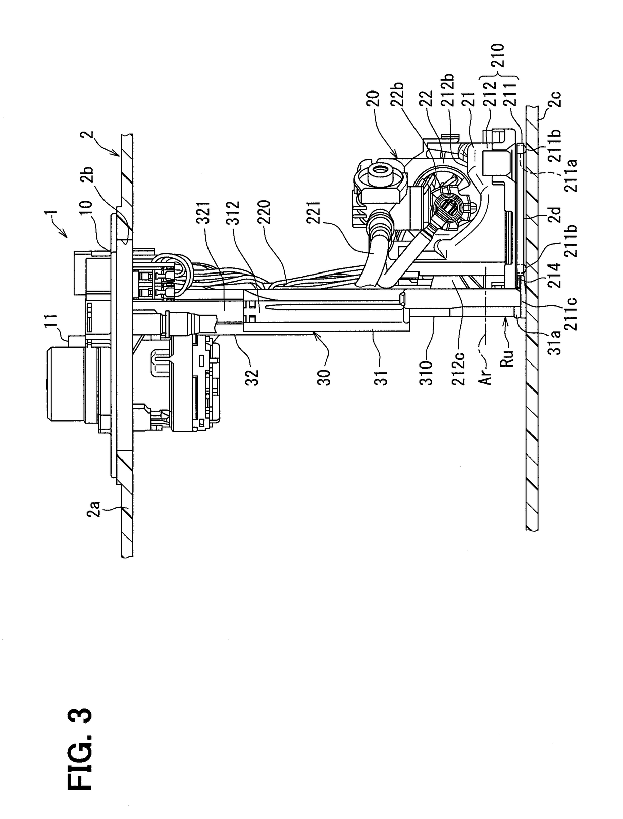
[0081]As shown in FIG. 1, a fuel supply device 1 according to a first embodiment of the present disclosure is installed to a fuel tank 2 and is thereby applied to an internal combustion engine 3 of a vehicle. The fuel supply device 1 supplies fuel, which is stored in the fuel tank 2, to the internal combustion engine 3 located at an outside of the fuel tank 2. Here, the fuel tank 2 is made of resin or metal and is shaped into a hollow form. An insertion hole 2b extends through an upper wall 2a of the fuel tank 2. The fuel supply device 1 is inserted into an inside of the fuel tank 2 through the insertion hole 2b. Under the above-described inserted state, the internal combustion engine 3, which is a supply destination of the fuel from the fuel supply device 1, may be a gasoline engine or a diesel engine. A top-to-bottom direction and a transverse direction of FIGS. 1 to 3, which show the inserted state of the fuel supply device 1 in the fuel tank 2, are respectively defined to corres...

second embodiment

[0123]A second embodiment of the present disclosure is a modification of the first embodiment.

[0124]As shown in FIGS. 21 and 22, at a lower stay 2031 of the second embodiment, not only the stress concentrating portion 313 is formed at the specific location Sc of the lower column segment 311, which serves as the first lower segment, but another stress concentrating portion 2313 is also formed at a specific location Sp of a lower tube segment 2312, which serves as a second lower segment. Here, as shown in FIG. 22, the specific location Sp is set in a range that is from the boundary 314, which is between the rotatable plate segment 310 and the hollow tubular portion 2312a of the lower tube segment 2312, to a location that is upwardly spaced from the boundary 314 by a predetermined distance in the hollow tubular portion 2312a of the lower tube segment 2312. As shown in FIGS. 21 and 22, the specific location Sp is placed immediately above the lower end part 31a of the lower stay 2031 and...

third embodiment

[0130]A third embodiment of the present disclosure is a modification of the first embodiment.

[0131]As shown in FIG. 24, a lower stay 3031 of the third embodiment includes an engaging portion 3315 at a location between the lower column segment 311, which serves as the first lower segment, and the lower tube segment 312, which serves as the second lower segment. In the lower stay 3031, the engaging portion 3315 is downwardly spaced from the upper end part 311c of the lower column segment 311 and the upper end part 312c of the lower tube segment 312. With the above-described construction, the engaging portion 3315 is engaged to and is stopped by the column-side lower end part 321c of the upper column segment 321 of the upper stay 32 when the slide fit length of the lower stay 3031 relative to the upper stay 32 is maximized, as shown in FIG. 24. At this time, the recessed bottom surface 320b of the upper stay 32 and the column-side upper end part 311c of the lower stay 31 are spaced fro...


PUM


Abstract

A fuel supply device configured to supply fuel from an inside of a fuel tank to an internal combustion engine includes: a cover body that is installed to an upper wall of the fuel tank; a pump unit that is placed on a bottom wall of the fuel tank and is configured to discharge the fuel from the inside of the fuel tank toward the internal combustion engine; and a coupling stay that couples between the cover body and the pump unit. The coupling stay includes: an upper stay that extends on a lower side of the cover body; and a lower stay that is installed to the pump unit and is slidably fitted to the upper stay in a top-to-bottom direction. A stress concentrating portion, which reduces a section modulus to concentrate a stress around the stress concentrating portion, is formed at a specific location of the lower stay.

Description

CROSS REFERENCE TO RELATED APPLICATION[0001]This application is based on and incorporates herein by reference Japanese Patent Application No. 2016-49806 filed on Mar. 14, 2016 and Japanese Patent Application No. 2016-182067 filed on Sep. 16, 2016.TECHNICAL FIELD[0002]The present disclosure relates to a fuel supply device that is configured to supply fuel from an inside of a fuel tank to an internal combustion engine.BACKGROUND ART[0003]Previously, an in-tank fuel supply device, which is placed in the inside of the fuel tank, is widely used at the internal combustion engine of a vehicle. In a device, which is disclosed in the patent literature 1 as this kind of fuel supply device, a coupling stay couples between a cover body, which is installed to an upper wall of the fuel tank, and a pump unit, which is placed on a bottom wall of the fuel tank and is configured to discharge the fuel from the inside of the fuel tank toward the internal combustion engine.[0004]The coupling stay of the...

Claims


Application Information

Patent Timeline
Patent Type & Authority Applications(United States)
IPC IPC(8): F02M37/10F02M37/00F02M63/02
CPCF02M37/106F02M37/0052F02D33/006F02M63/0275F02M37/0082F02D41/3082
Inventor ADACHI, RUIHAZAMA, TADASHIHAYASHI, NORIHIROAKIBA, TAKASHIFUKUOKA, SHINGO
Owner AISAN IND CO LTD
Why Eureka
Try Eureka