
Three-dimensional modeling from optical capture

a technology of optical capture and three-dimensional modeling, applied in the field of three-dimensional modeling, can solve the problems of reducing affecting the usability of the project site, so as to cost, reduce the cost, and reduce the amount of tim

Active Publication Date: 2019-01-24
FUSCOE ENG INC
View PDF7 Cites 17 Cited by
  • Summary
  • Abstract
  • Description
  • Claims
  • Application Information

AI Technical Summary

Benefits of technology

The present patent provides methods for creating a 3D model that save time and money compared to traditional methods. The methods allow for faster and less expensive generation of a 3D model.

Problems solved by technology

However, there may be challenges in generating a usable 3D model of the project site.
Given the speed at which the laser scanner can capture points, the laser scanner may create a dense point cloud of data.
In particular, buildings, terrain features, and other obstacles may block views from any given single vantage point.
In accordance with at least some embodiments disclosed herein is the realization that this procedure is a time consuming process, and often introduces human error.

Method used


Image

  • Three-dimensional modeling from optical capture
  • Three-dimensional modeling from optical capture
  • Three-dimensional modeling from optical capture

Examples


Embodiment Construction

[0032]It is understood that various configurations of the subject technology will become readily apparent to those skilled in the art from the disclosure, wherein various configurations of the subject technology are shown and described by way of illustration. As will be realized, the subject technology is capable of other and different configurations and its several details are capable of modification in various other respects, all without departing from the scope of the subject technology. Accordingly, the summary, drawings and detailed description are to be regarded as illustrative in nature and not as restrictive.

[0033]The detailed description set forth below is intended as a description of various configurations of the subject technology and is not intended to represent the only configurations in which the subject technology may be practiced. The appended drawings are incorporated herein and constitute a part of the detailed description. The detailed description includes specifi...


PUM


Abstract

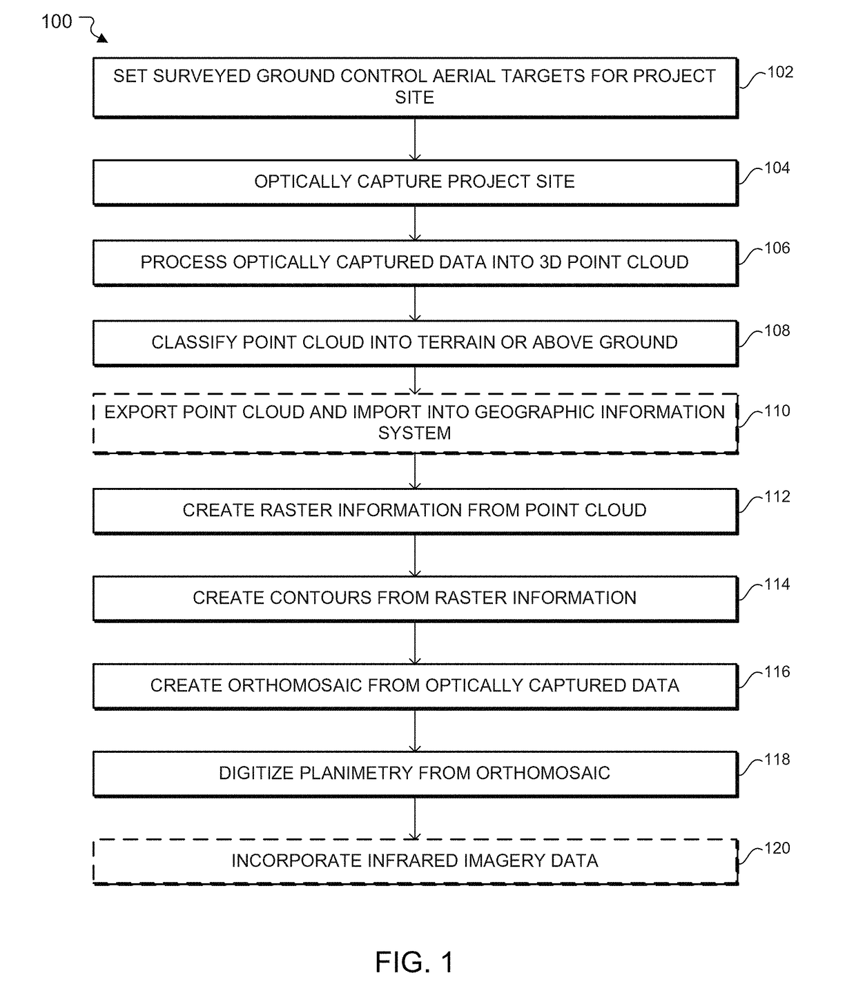
The subject system provides for the generation of a three-dimensional (3D) model from optical capture including the generation of the 3D model from point cloud data migration. The subject system includes generating a point cloud based on optically captured data of a project site. The subject system also includes generating raster information from the point cloud, and creating surface contours based on the raster information. The subject system also includes creating a 3D model based on the surface contours.

Description

BACKGROUNDTechnical Field[0001]The present application relates generally to three-dimensional (3D) models, and more particularly to 3D modeling from optical capture.Description of the Related Art[0002]When designing a building or other structure on a project site, a 3D model of the project site provides architects and other designers with a virtual project site to aid in design. However, there may be challenges in generating a usable 3D model of the project site.[0003]The virtual project site may first be surveyed, for example a topographic survey. Conventional surveying techniques include laser surveying. Laser surveying involves using a laser scanner. The laser scanner sends out a laser beam all over a field of view of the laser scanner. The laser beam hits a surface and is reflected back to the laser scanner. For every surface that the laser hits, a point in space is recorded. Given the speed at which the laser scanner can capture points, the laser scanner may create a dense poin...

Claims


Application Information

Patent Timeline
Patent Type & Authority Applications(United States)
IPC IPC(8): G06T17/05G06T7/564G06T15/04
CPCG06T17/05G06T2200/04G06T15/04G06T7/564G06T2210/56G01C11/30G01C11/02
Inventor FUSCOE, PATRICK R.IJAMS, MICHAEL A.VEGA, MATTHEW H.
Owner FUSCOE ENG INC
Learn More