Over current protection circuit

a protection circuit and over current technology, applied in the field of power supply, can solve the problems of resistor burning out, operator's electric shock and fire phenomena, further damage to electronic products, etc., and achieve the effect of promoting power efficiency and reducing failure risk and fir

Active Publication Date: 2019-01-24
SHENZHEN CHINA STAR OPTOELECTRONICS SEMICON DISPLAY TECH CO LTD
View PDF0 Cites 6 Cited by
  • Summary
  • Abstract
  • Description
  • Claims
  • Application Information

AI Technical Summary

Benefits of technology

[0032]In conclusion, the present invention achieves the over current protection for the large current output of the power supply to promote the efficiency of the power and to reduce the risk of failure and fire of the power due to the resistance current limitation.

Problems solved by technology

Otherwise, it may cause further damage to the electronic product or even cause the operator's electric shock and the fire phenomena, therefore, the over current protection function of the switching power supply must be perfect.
However, when the over current protection circuit design of a high power supply or an ultra high power supply adopts an over current protection by a resistor, it may cause the resistor to burn out due to the over power and to cause a fire, which is urgent to be improved.

Method used


Image

  • Over current protection circuit

Examples


Embodiment Construction

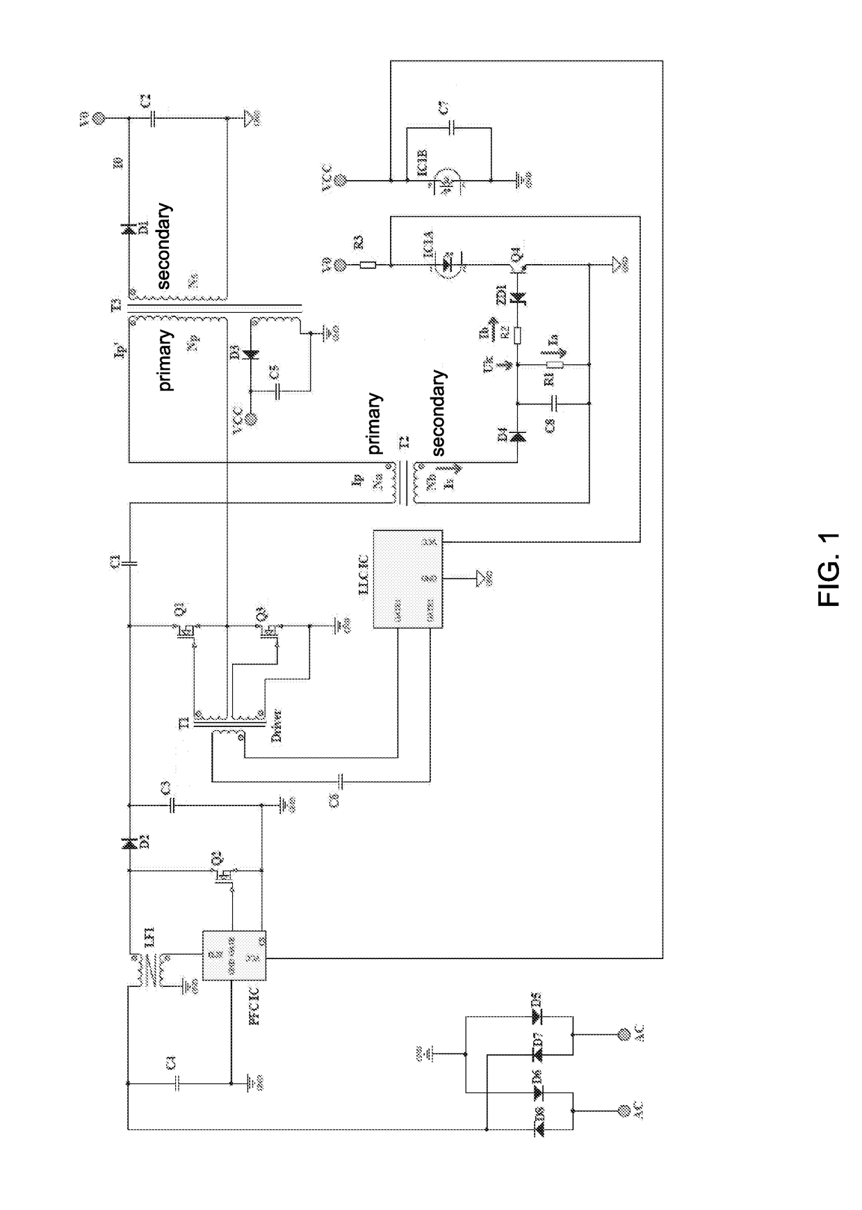
[0036]Please refer to FIG. 1, which is a circuit diagram of one preferred embodiment of an over current protection circuit according to the present invention. The present invention provides an over current protection circuit comprising a current transformer to combine the over current protection function in kinds of power supplies. The specifications of the respective components and the key current, the key voltages in the embodiment shown in FIG. 1 can be referred to labels in FIG. 1. The entire power supply in FIG. 1 further comprises a power factor correction chip (PFC IC) and a line level control chip (LLC IC). A PFC circuit surrounds the PFC chip. A LLC circuit surrounds the LLC chip. The external alternating current power is inputted and processed by a transformer T1, a transformer T3, the PFC chip and the LLC chip, and then outputs a voltage externally through a first voltage output end V0 coupled to a secondary winding of the transformer T3. The secondary winding of the tran...


PUM


Abstract

An over current protection circuit, comprising: a current transformer, having a primary winding connected in series with a primary winding of a power supply transformer and a secondary winding, of which one end is grounded and the other end is coupled to a diode anode; a first resistor, having one end coupled to a diode cathode and the other end grounded; a second resistor, having one end coupled to the diode cathode and the other end coupled to a zener diode cathode; a triode, having a base coupled to a zener diode anode, an emitter grounded and a collector coupled to a light emitter cathode; wherein a light emitter anode is coupled to a LLC chip and a first voltage output end in the power supply; an output end of a light receiver is ground, an input end is coupled to a second voltage output end and a PFC chip.

Description

FIELD OF THE INVENTION[0001]The present invention relates to a power supply field, and more particularly to an over current protection circuit.BACKGROUND OF THE INVENTION[0002]As concerning the power supply device for all electronic products, except the performance has to meet the requirements of the power supply products, the protection measures of the power supply, such as over voltage protection, over current protection, over temperature protection. Once the electronic product fails, such as the short circuit at the input side or the open circuit at the output side in the electronic product occurs, the output voltage of the power supply must be turned off to protect the power device and the output side device from being burned. Otherwise, it may cause further damage to the electronic product or even cause the operator's electric shock and the fire phenomena, therefore, the over current protection function of the switching power supply must be perfect.[0003]In the existing power c...

Claims


Application Information

Patent Timeline
Patent Type & Authority Applications(United States)
IPC IPC(8): H02H3/08
CPCH02H3/08H02M1/32H02H7/125H02M1/4225H02M3/33553Y02B70/10H02M1/0009H02H7/12
Inventor YANG, YONGLIU, FANGYUN
Owner SHENZHEN CHINA STAR OPTOELECTRONICS SEMICON DISPLAY TECH CO LTD
Why Eureka
Try Eureka