Wireless inductive power transfer

a technology of inductive power transfer and wires, which is applied in the direction of transformers/inductance coils/windings/connections, transportation and packaging, electric vehicles, etc., can solve the problems of voltages being induced that exceed the level considered unsuitable for the circuitry of power receivers, over-voltage conditions at power receivers, etc., and achieve quick increase in couplings and efficient power control.

Active Publication Date: 2019-01-24
KONINKLJIJKE PHILIPS NV
View PDF3 Cites 22 Cited by
  • Summary
  • Abstract
  • Description
  • Claims
  • Application Information

AI Technical Summary

Benefits of technology

[0032]The approach may provide efficient power control during active power transfer while still preventing or mitigating e.g. over-voltage conditions resulting from sudden changes in the operating conditions, such as a quick increase in the coupling between the power transmitter and the power receiver.
[0033]In the power transfer ph

Problems solved by technology

In particular, the inventors have realized that many current power transfer systems (such as ones following the Qi specifications) include a power control loop which may in some scenarios result in over-voltage conditions occurring at power receivers due to sudden changes in the coupling between the power tra

Method used


Image

  • Wireless inductive power transfer
  • Wireless inductive power transfer
  • Wireless inductive power transfer

Examples


Embodiment Construction

[0080]The following description focuses on embodiments of the invention applicable to a wireless power transfer system utilizing a power transfer approach such as known from the Qi specification. However, it will be appreciated that the invention is not limited to this application but may be applied to many other wireless power transfer systems.

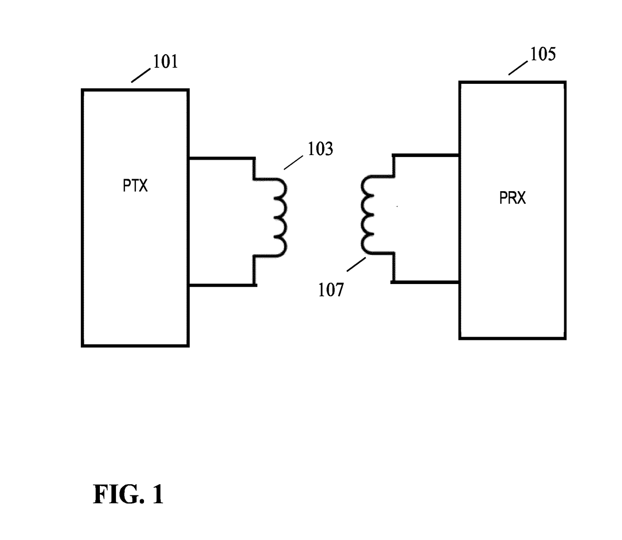
[0081]FIG. 1 illustrates an example of a power transfer system in accordance with some embodiments of the invention. The power transfer system comprises a power transmitter 101 which includes (or is coupled to) a transmitter coil / inductor 103. The system further comprises a power receiver 105 which includes (or is coupled to) a receiver coil / inductor 107.

[0082]The system provides a wireless inductive power transfer from the power transmitter 101 to the receiver 105. Specifically, the power transmitter 101 generates a wireless inductive power transfer signal (also referred to as a power transfer signal, power transfer signal or an inductive po...


PUM


Abstract

A power transmitter (101) of a wireless power transfer system comprises a resonance including a transmitter coil (103) for generating a power transfer signal for wirelessly transferring power to a power receiver (105). Further, a driver (1303) generates a drive signal for the resonance circuit (201) and a message receiver (1305) is arranged to receive messages from the power receiver (105). A power loop controller (1307) implements a power control loop by adapting the power of the drive signal in response to power control messages received from the power receiver (105). However, the regulation is subject to a constraint of at least one of a current or voltage of the resonance circuit and a power of the drive signal being below a maximum limit. Further, the power transmitter (101) comprises an adapter (1309) which adapts the maximum limit in response to a load indication indicative of a loading of the power transfer signal by the power receiver (105).

Description

FIELD OF THE INVENTION[0001]The invention relates to inductive power transfer and in particular, but not exclusively, to a power transmitter providing inductive power transfer using elements compatible with the Qi Specifications for wireless power transfer systems.BACKGROUND OF THE INVENTION[0002]Most present day systems require a dedicated electrical contact in order to be powered from an external power supply. However, this tends to be impractical and requires the user to physically insert connectors or otherwise establish a physical electrical contact. Typically, power requirements also differ significantly, and currently most devices are provided with their own dedicated power supply resulting in a typical user having a large number of different power supplies with each power supply being dedicated to a specific device. Although, the use of internal batteries may avoid the need for a wired connection to a power supply during use, this only provides a partial solution as the batt...

Claims


Application Information

Patent Timeline
IPC IPC(8): H02J50/12H01F27/28H02J7/02H02J50/80
CPCH02J50/12H01F27/28H02J7/025H02J50/80
Inventor STARING, ANTONIUS ADRIAAN MARIAVAN WAGENINGEN, ANDRIES
Owner KONINKLJIJKE PHILIPS NV
Why Eureka
Try Eureka