
Refrigeration cycle apparatus

a technology of cycle apparatus and refrigeration cycle, which is applied in the direction of lighting and heating apparatus, refrigeration machines, compression machines with reversible cycles, etc., can solve the problems of limited use of refrigeration agents containing chlorine such as cfc and hcfc, and achieves the effects of sufficient reliability, low influence on global warming, and sufficient performan

Inactive Publication Date: 2019-01-31
MITSUBISHI ELECTRIC CORP
View PDF4 Cites 3 Cited by
  • Summary
  • Abstract
  • Description
  • Claims
  • Application Information

AI Technical Summary

Benefits of technology

The invention is about a refrigeration system that is environmentally friendly and reliable. The technical effects of this invention are that it reduces the impact on global warming and ensures high levels of performance and reliability.

Problems solved by technology

Refrigerants containing chlorine such as CFC and HCFC, however, are currently restricted in use, because they have considerable influences on the ozone layer in the stratosphere (influences on global warming).

Method used


Image

  • Refrigeration cycle apparatus
  • Refrigeration cycle apparatus
  • Refrigeration cycle apparatus

Examples


embodiment 1

Modification of Embodiment 1

[0067]The present modification differs from Embodiment 1 in that the composition of refrigerant is further limited within the range of Embodiment 1. In other respects, the basic configuration is the same as that of Embodiment 1, and the description of the same configuration is not repeated. According to the present modification, the refrigerant working pressure is lower than that of the conventional refrigerant, and additionally the performance equivalent to or higher than the performance of R410A (higher than Embodiment 1) can be obtained.

[0068]FIG. 4 is a ternary composition diagram showing a composition ratio between the three components (R32, HFO1123, and R1234yf) contained in the refrigerant in the present modification. In FIG. 4, the mass ratio between the three components falls in a range (hatched portion in FIG. 4) enclosed by a third straight line connecting point A to point D, a fourth straight line connecting point D to point E, and a second cu...

embodiment 2

Modification of Embodiment 2

[0085]The present modification differs from Embodiment 2 in that the composition of refrigerant is further limited within the range of Embodiment 2. In other respects, the basic configuration is the same as that of Embodiment 2, and the description of the same configuration is not repeated. According to the present modification, the refrigerant working pressure is lower than that of the conventional refrigerant, and additionally the performance equivalent to or higher than the performance of R410A (performance higher than Embodiment 2) can be obtained.

[0086]FIG. 8 is a ternary composition diagram showing a composition ratio between the three components (R32, HFO1123, and R1234ze) contained in the refrigerant in the present modification. In FIG. 8, the mass ratio between the three components falls in a range (hatched portion in FIG. 8) enclosed by a third straight line connecting point A to point D, a fourth straight line connecting point D to point E, and...

embodiment 3

[0093]Refrigerant

[0094]A refrigeration cycle apparatus according to the present embodiment differs from Embodiment 1 in that the composition ratio between three components contained in refrigerant is set so that the refrigerant working pressure is lower than that of a conventional refrigerant (R404A) different from that in Embodiment 1. In other respects, the basic configuration is the same as that of Embodiment 1, and the description of the same configuration is not repeated.

[0095]R404A is a pseudo-azeotropic refrigerant mixture of pentafluoroethane (R125), 1,1,1-trifluoroethane (R143a) and 1,1,1,2-tetrafluoroethane (R134a).

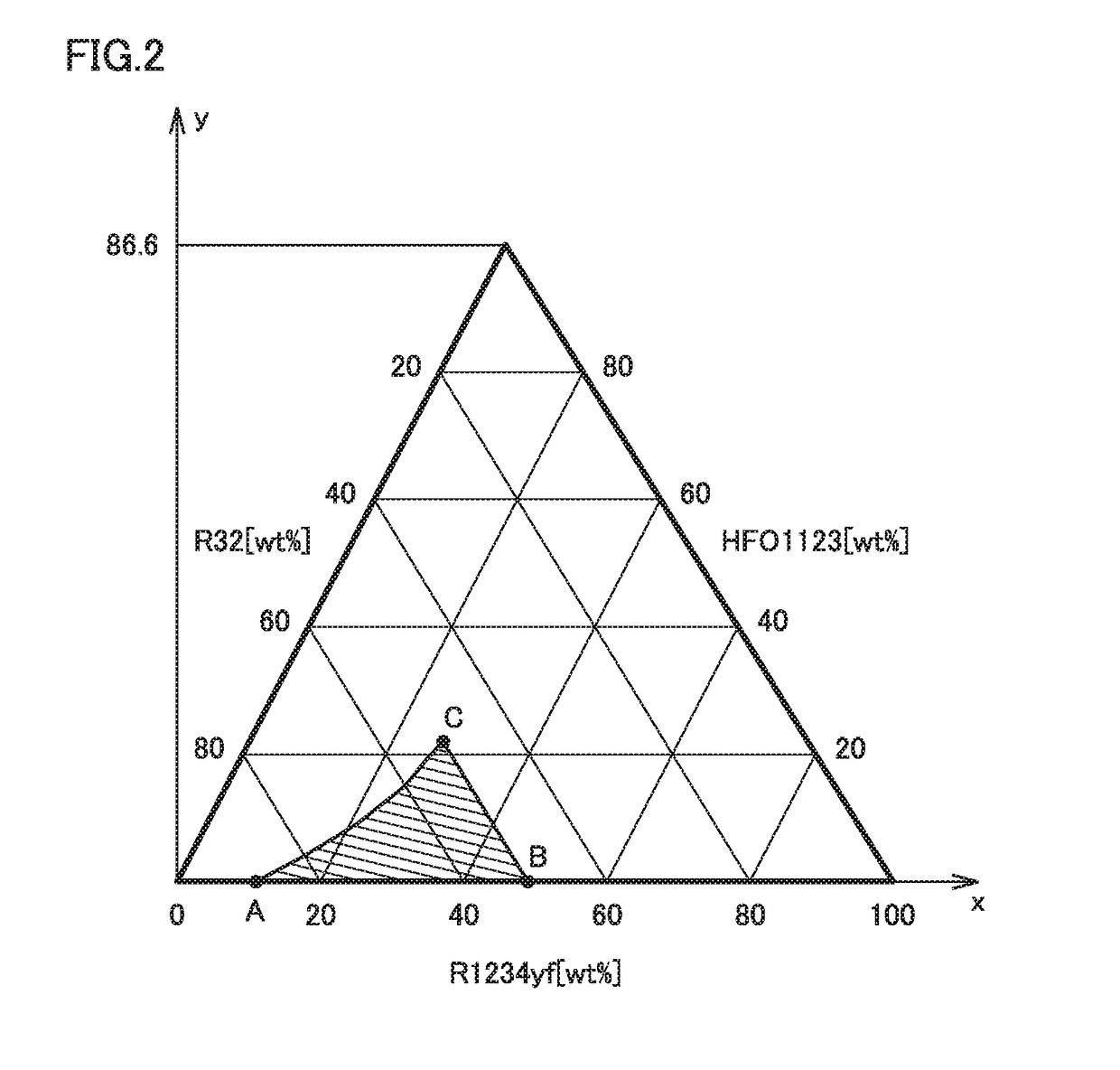
[0096]FIG. 10 is a ternary composition diagram showing a composition ratio between the three components (R32, HFO1123, and R1234yf) contained in the refrigerant of the present embodiment. In FIG. 10, the mass ratio between the three components falls in a range (hatched portion in FIG. 10) enclosed by a first straight line connecting point A to point B, a second ...


PUM


Abstract

A refrigeration cycle apparatus of the present invention includes a refrigeration circuit having a compressor, an outdoor heat exchanger, an indoor heat exchanger, and an expansion valve. Refrigerant is enclosed in the refrigeration circuit. The refrigerant contains three components: R32, R1234yf, and HFO1123. In a composition diagram in which a mass ratio between the three components is represented by triangular coordinates, the mass ratio between the three components falls in a range enclosed by: a first straight line connecting a point A to a point B; a second straight line connecting the point B to a point C; and a first curve connecting the point C to the point A. Each of all the three components has a mass ratio of more than 0% by mass.

Description

TECHNICAL FIELD[0001]The present invention relates to a refrigeration cycle apparatus.BACKGROUND ART[0002]Refrigerants having been used for air conditioner, refrigerator, and the like are those such as chlorofluorocarbon (CFC) and hydrochlorofluorocarbon (HCFC). Refrigerants containing chlorine such as CFC and HCFC, however, are currently restricted in use, because they have considerable influences on the ozone layer in the stratosphere (influences on global warming).[0003]In view of this, hydrofluorocarbon (HFC) that is chlorine free and has low influence on the ozone layer has become used as refrigerant. As an example of such HFC, difluoromethane (also called methylene fluoride, Freon-32, HFC-32, R32, for example, referred to as “R32” hereinafter) is known (see Patent Document 1: Japanese Patent No. 3956589). Other known HFCs are tetrafluoroethane and R125 (1,1,1,2,2-pentafluoroethane), for example. In particular, R410A (a pseudo-azeotropic refrigerant mixture of R32 and R125) hav...

Claims


Application Information

Patent Timeline
IPC IPC(8): C09K5/04
CPCC09K5/045C09K2205/122C09K2205/126C09K2205/22F25B13/00F25B9/006F25B1/00
Inventor NISHIYAMA, TAKUMITANAKA, KOSUKE
Owner MITSUBISHI ELECTRIC CORP
Learn More