Method and device of batch transferring micro components

Active Publication Date: 2019-01-31
INNOSERV
View PDF0 Cites 10 Cited by
  • Summary
  • Abstract
  • Description
  • Claims
  • Application Information

AI Technical Summary

Benefits of technology

[0019]Accordingly, the adhesive material dips with the micro components, is cooled in a temperature controlling manner, and is heated so as to melt the adhesive ma

Problems solved by technology

1. Regarding die bonding to an LED light bar, defective pixel occurs on the LED light bar, so it is difficult to embody millions of micro LEDs onto a display. To overcome such a problem, LCD and OLED are produce in batch so as to enhance production yield.
2. It is suitable to flip chip LEDs on a micro LED display because of small size and easy production, thus miniaturizing micro LEDs without metal wires, and decreasing a distance between any two adjacent LEDs. It is to be

Method used


Image

  • Method and device of batch transferring micro components
  • Method and device of batch transferring micro components
  • Method and device of batch transferring micro components

Examples


Example

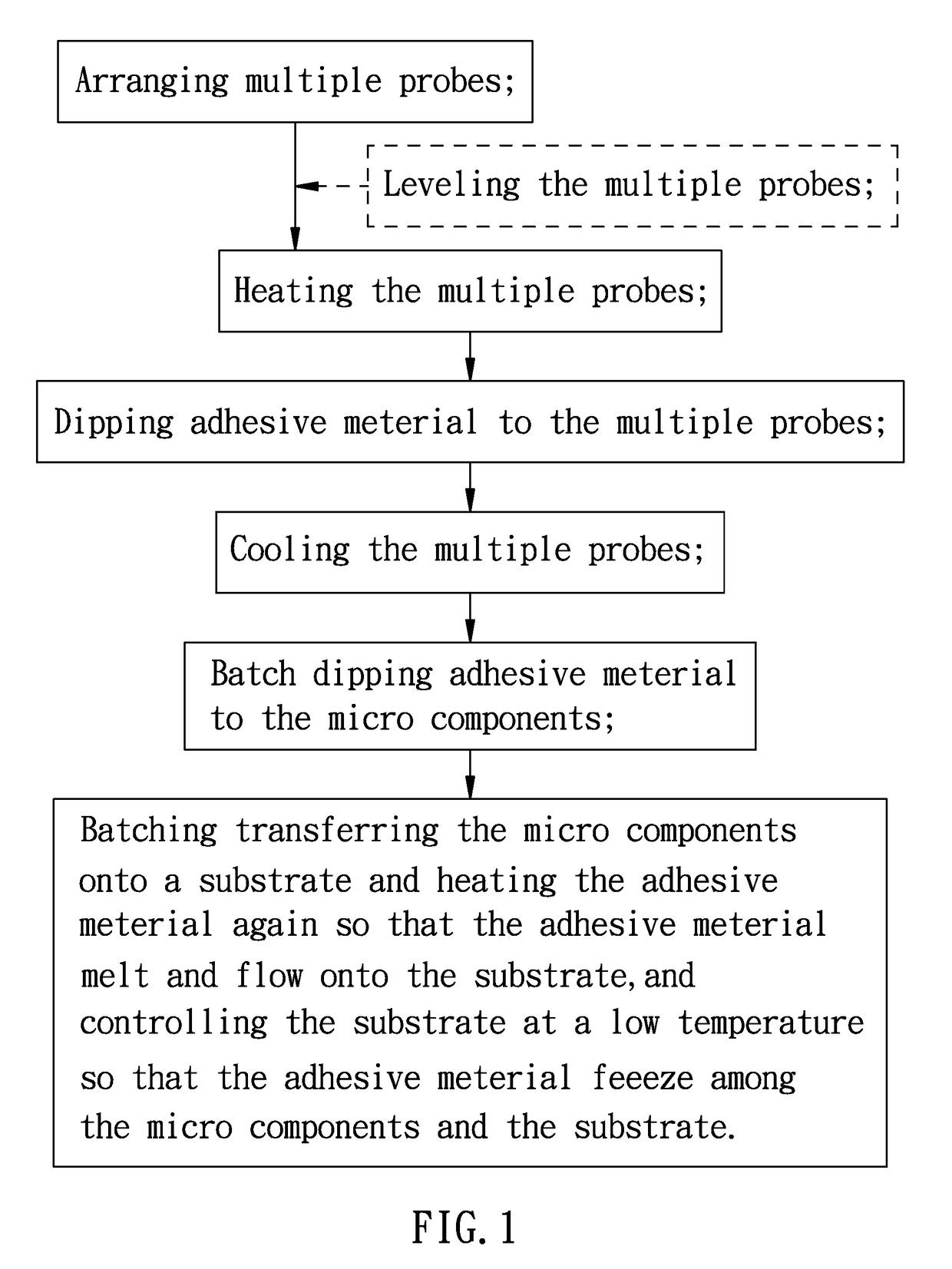
[0035]With reference to FIGS. 1 and 2, a method of batch transferring micro components according to a preferred embodiment of the present invention comprises steps of:

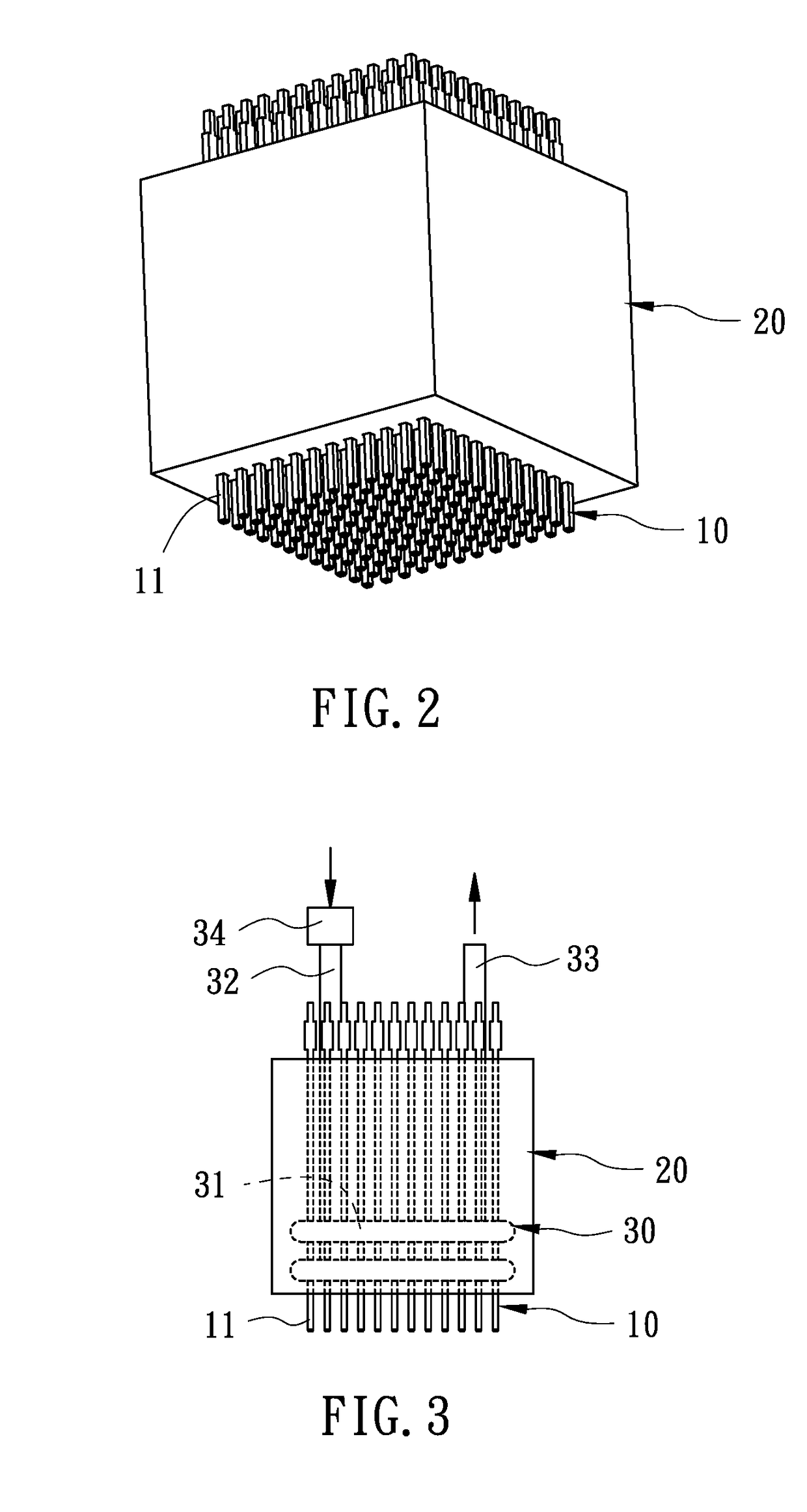
[0036]A. arranging multiple probes 10 in array on a carrying unit 20, and extending multiple columns 11 of the multiple probes 10 out of a bottom of the carrying unit 20, as shown in FIG. 2, and leveling the multiple probes 10 on the carrying unit 20 so that the multiple columns 11 flush with one another on the bottom of the carrying unit 20, wherein the multiple probes 10 are leveled in a grinding manner based on a required execution frequency;

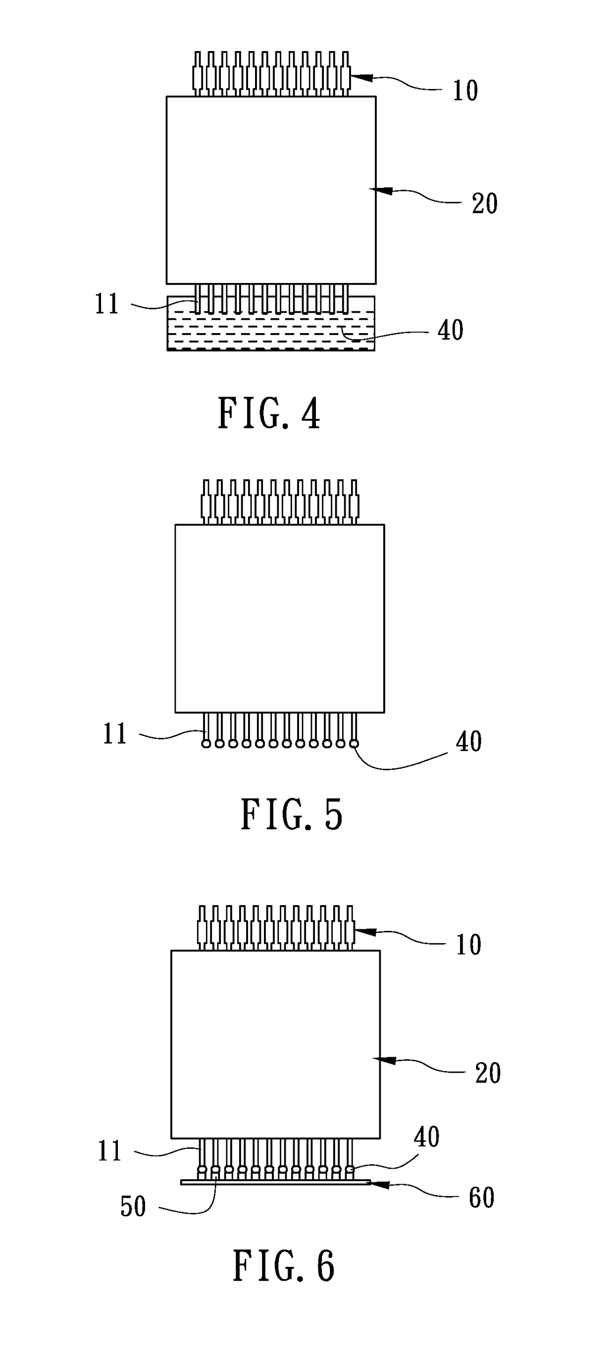
[0037]B. heating the multiple probes 10 by feeding hot water into a temperature control conduit 30 in the carrying unit 20, as illustrated in FIG. 3, wherein the temperature control conduit 30 is defined by a winding channel 31 around the multiple probes 10, an inlet segment 32 and an outlet segment 33 of the winding channel 31 extend out of a top of the carrying unit 20, and th...


PUM


Abstract

A method of batch transferring micro components comprising steps of: A. arranging multiple probes in array on a carrying unit and extending multiple columns of the multiple probes out of a bottom of the carrying unit; B. providing a temperature control conduit in the carrying unit into which hot water is fed; C. driving the carrying unit so that the multiple columns of the multiple probes dip an adhesive material; D. feeding cold water into the temperature control conduit; E. moving the carrying unit on micro components and pressing the multiple probes of the carrying unit downward; F. moving the carrying unit onto a substrate and pressing the micro components to desired positions respectively; and G. heating adhesive material again as pressing the micro components and controlling the substrate at a low temperature so that the adhesive material freezes among the micro components and the substrate.

Description

BACKGROUND OF THE INVENTION1. Technical Field[0001]The present invention relates to a method of mass transferring micro components, and more particularly to a method and a device of batch transferring the micro components.2. Description of Related Art[0002]With maturation and evolution of light-emitting diodes (LEDs), the LEDs are laminated, miniaturized, arrayed nowadays, for example, a size of each LED is miniaturized within 1 μm to 10 μm so as to produce micro LED display.[0003]The micro LED has more specifications than LCD and the same image quality as OLED, but it has defects as follows:[0004]1. Regarding die bonding to an LED light bar, defective pixel occurs on the LED light bar, so it is difficult to embody millions of micro LEDs onto a display. To overcome such a problem, LCD and OLED are produce in batch so as to enhance production yield.[0005]2. It is suitable to flip chip LEDs on a micro LED display because of small size and easy production, thus miniaturizing micro LEDs...

Claims


Application Information

Patent Timeline
IPC IPC(8): H01L21/677H01L21/683
CPCH01L21/67754H01L21/6836H01L2221/68363H01L21/6835H01L2221/68322H01L2221/68354H01L24/95H01L33/0095H01L21/67109H01L21/67144H01L21/67248H01L2924/12041H01L2224/7598H01L24/743H01L2224/756H01L2224/75252H01L2224/2731H01L24/27H01L2224/2919H01L24/29H01L24/83H01L24/32H01L2224/32225H01L2224/75303H01L2224/32105H01L24/75H01L2224/75502H01L2224/95H01L2224/8385H01L2224/7531H01L2924/00012H01L2924/00014H01L2224/83
Inventor WU, CHIH-MENG
Owner INNOSERV
Why Eureka
Try Eureka