Air circulating device below steam generator of nuclear reactor

Inactive Publication Date: 2018-01-04
MOON & DUG
View PDF0 Cites 2 Cited by
  • Summary
  • Abstract
  • Description
  • Claims
  • Application Information

AI Technical Summary

Benefits of technology

[0034]Further, preferably in the present invention, the sleeve has a Venturi passage formed therein such that the Venturi Effect is imparted to air passing through the sleeve, and the speed of flowing air is accelerated to improve air circulating effects.
[0035]Still further, preferably in the present invention, the sleeve has a neck portion formed at and proximal to a top end portion of the sleeve and having a decreasing inner diameter, such that the Venturi Effect is imparted, and the speed of flowing air is accelerated to improve air circulating effects in the stagnated air area.
[0036]According to the present invention, a through-hole is formed in the center of a sliding base supporting a steam generator, a sleeve that is aligned with the through-hole and vertically mounted is included so as to introduce external air from below the sliding base, and a skirt support defines at least one vent hole so as to naturally circulate high-temperature heat in a stagnated air area to the outsi

Problems solved by technology

In particular, thermal deformation of the sliding base (30) suppresses free movement caused by thermal expansion of the sliding base (30) that occurs during power plant operation, or causes interference with surrounding structures at the upper portion of the steam generator (1), thereby leading to structural vibration of the steam generator (1) and a coolant pump.
Such structural vibration causes fretting wear and vibration stress to the steam generator (1), and prolonged operation induces fatigue in small diameter pipes which are subjected to boric acid embrittlement due to the accumulation of boric acid, such that leakage of bor

Method used


Image

  • Air circulating device below steam generator of nuclear reactor
  • Air circulating device below steam generator of nuclear reactor
  • Air circulating device below steam generator of nuclear reactor

Examples


Example

[0045]Hereinafter, preferred embodiments of the present invention will be described in further detail with reference to the drawings.

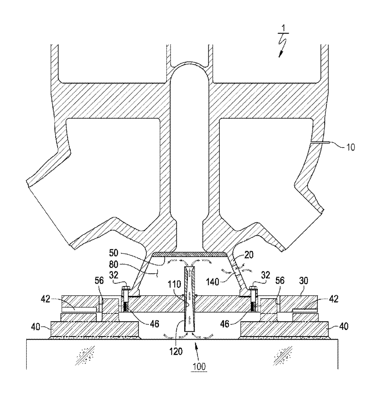
[0046]An air circulating sleeve device (100) at the lower portion of a steam generator according to the present invention is a device for preventing thermal deformation of a sliding base (30) supporting a nuclear reactor steam generator (1) and preventing vibrating of the nuclear reactor.

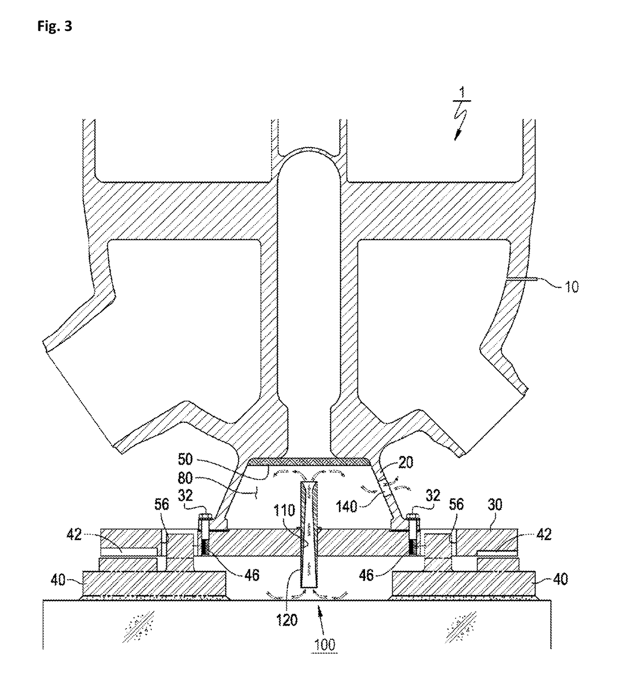
[0047]The air circulating sleeve device (100) at the lower portion of the steam generator according to the present invention, as illustrated in FIGS. 3 and 4, is a structure having a through-hole (110) formed in the center of the sliding base (30), and a sleeve (120) aligned with the through-hole (110) and mounted vertically.

[0048]In particular, the air circulating sleeve device (100) at the lower portion of the steam generator according to the present invention, as illustrated in FIG. 4, is a structure differing from existing structures in that the sleeve (120) is mou...


PUM


Abstract

The present invention provides an air circulating sleeve device that is provided below a steam generator to prevent thermal deformation of a sliding base that supports the steam generator of a nuclear reactor, the air circulating sleeve device comprising: a through-hole formed at the center of the sliding base; and a sleeve vertically mounted so as to be aligned with the through-hole, wherein thermal deformation of the sliding base is prevented by performing natural cooling by introducing external air below the sliding base into a stagnated air area inside the sliding base and a skirt support through the sleeve, and the skirt support includes at least one vent hole such that the stagnated air area inside the sliding base and the skirt support is exposed to the air outside the skirt support, and natural circulation of air is performed through the vent hole.

Description

FIELD OF THE INVENTION[0001]The present invention relates to a sleeve device for circulating air in a stagnated air area disposed below a steam generator of a nuclear reactor and, more particularly, to an air circulating sleeve device below a steam generator of a nuclear reactor, wherein the air circulating sleeve device is for preventing vibrating of the nuclear reactor due to thermal expansion deformation of a sliding base, by naturally circulating air through the Venturi Effect by having an air circulating sleeve mounted at the center of the sliding base supporting the steam generator of the nuclear reactor, naturally cooling a stagnated air area inside a stay cylinder and a skirt support of the steam generator, and effectively preventing the transfer of high-temperature heat from the steam generator to the sliding base.BACKGROUND OF THE INVENTION[0002]In general, Korean examples of nuclear reactors include System Plus 80 (Hanbit units 3 and 4) by Conbustion Engineering (CE), Kor...

Claims


Application Information

Patent Timeline
IPC IPC(8): G21C15/26G21C15/16
CPCG21C15/16G21C15/26F22B1/00G21D1/006G21D1/02Y02E30/30Y02E30/00
Inventor MOON, IN DUG
Owner MOON & DUG
Why Eureka
Try Eureka