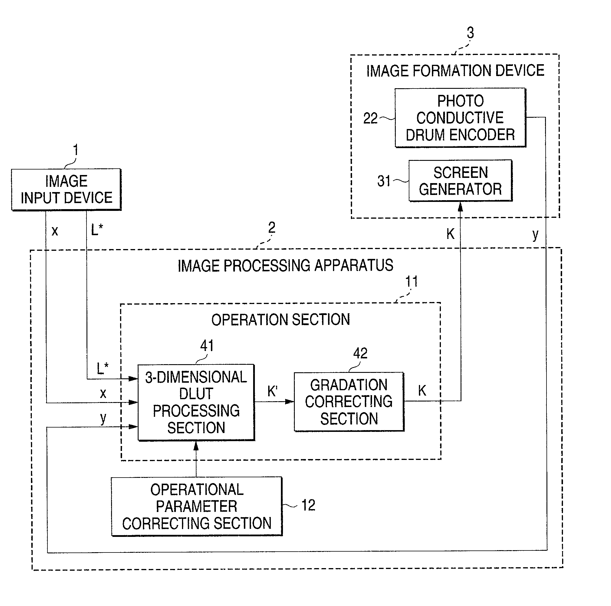
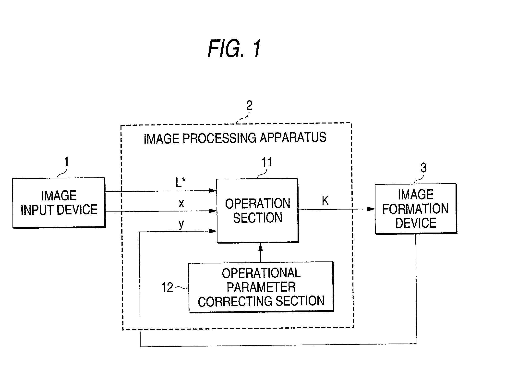
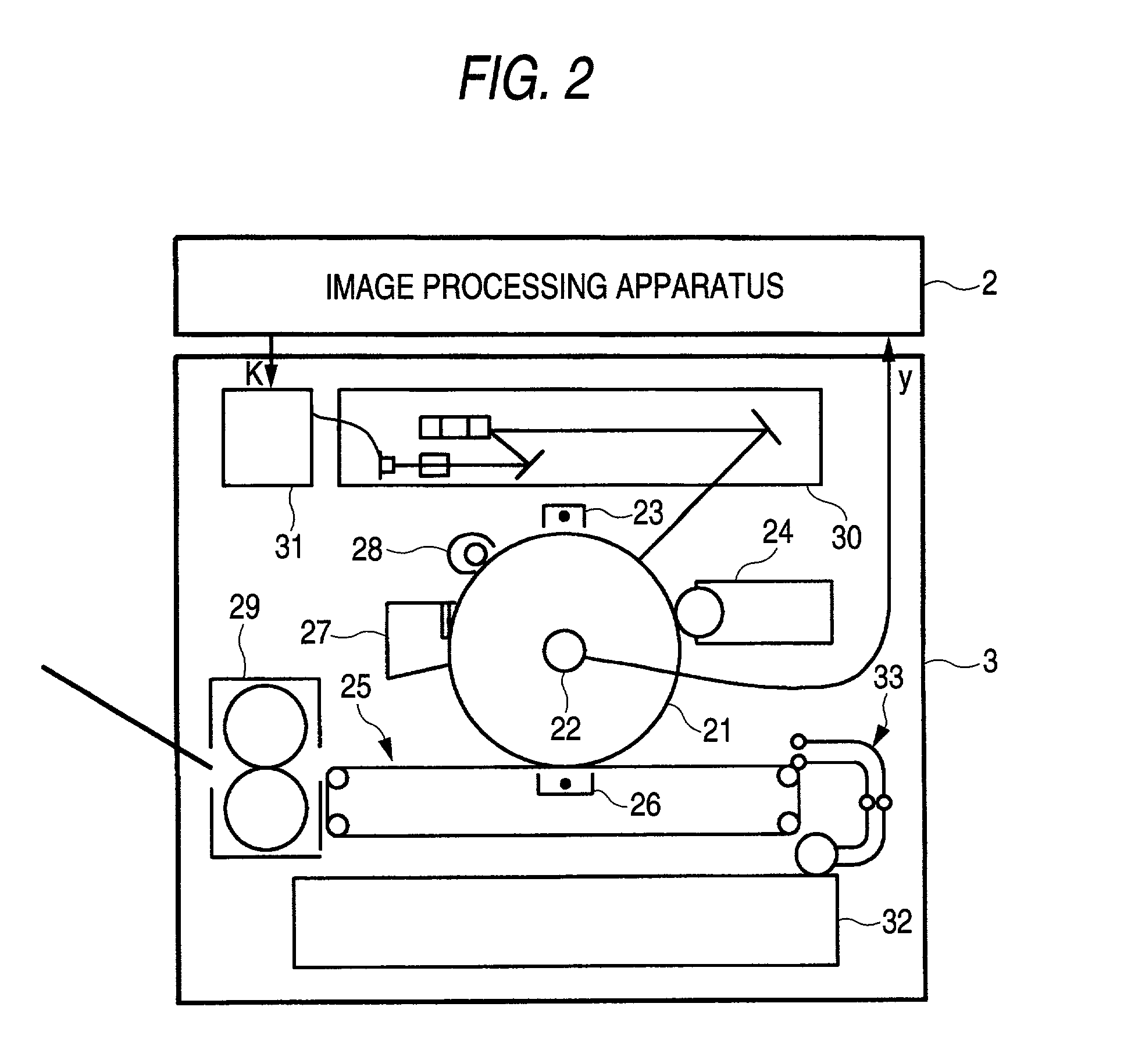
However, the color reproducibility is different every image formation device utilized in printout and when an input digital picture signal is output as it is, faithful
color reproduction cannot be expected.
However, there is a problem that in case the method of using matrix operation has input-output characteristics high in nonlinearity, it is difficult to acquire the
high color conversion precision.
However, the method of using the neural network has a problem that as the amount of operation is much, it is not suitable for real
time processing.
However, in an image formation device the in-plane uniformity of which is low, even if color conversion is made using DLUT, it is difficult to realize
high color conversion precision.
Therefore, in electrophotography, sufficiently
high color conversion precision is not acquired.
However, as colorimetric color has an error in an image formation device the in-plane uniformity of which is low, color conversion precision exceeding the in-plane uniformity of the image formation device cannot be acquired in principle.
Therefore, in electrophotography, even if color conversion is made by using DLUT generated based upon correspondence with an input
chrominance signal and an output colorimetric value, enough precision cannot be acquired.
Further, there is a problem that when DLUT is applied to color conversion in an image formation device the in-plane uniformity of which is low and a color conversion parameter is determined in consideration of color conversion precision, the color conversion parameter has a
random error and the continuity of a color conversion characteristic is deteriorated.
However, according to this method, the effect of an error by color variation in the plane cannot be removed in principle.
That is, for the color conversion parameter value of DLUT, an error by in-plane color variation is considered, however, an error by in-plane color variation when recording is actually performed based upon an output
chrominance signal to which color conversion is applied by using DLUT occurs.
Therefore, there is a problem of color conversion precision that an error equivalent to color variation is left.
As described above, in color conversion according to the related art, even if high-precision color conversion represented by DLUT is applied, high color conversion precision cannot be acquired in an image formation device the in-plane uniformity of which is low.
Generally, the photo conductor has in-plane unevenness in the charge and optical sensitivity and has a problem that even if uniform charge, uniform
exposure and uniform developing are performed, dispersion occurs in density thereof depending upon a two-dimensional location.
The cause in which in-plane unevenness is caused in the charge and the optical sensitivity of the photo conductor greatly depends upon the manufacturing method and the
structural problem of the photo conductor.
Therefore, the thickness is required to be unified, however, as the sensitive material is required to be precisely applied in units of micron for that purpose, the cost of the photo conductor is increased and the method is not realistic.
Further, there is a problem that it is difficult to uniformly charge and
expose a photo conductor and to uniformly develop on the photo conductor.
Therefore, high mechanical precision and rigidity are required for a frame for fixing the developing roll and the photo conductor and there is a problem that the cost of the image formation device is increased and the image formation device is large-sized.
In case that a
laser scanner is used for
exposure, a
beam diameter on a photo conductor in a direction of horizontal scanning differs depending upon positional precision between the optical
scanner and the photo conductor and unevenness is caused in the
electric potential of the photo conductor in the direction of horizontal scanning.
Generally, as the volume resistivity of the transfer belt is not uniform in a plane of the belt, there is a problem that color variation is caused depending upon a location in a two-dimensional plane.
To adjust the volume resistivity of the transfer belt,
carbon black is mixed in plastic such as
polyimide which is a base of the transfer belt, however, at that time, as the
carbon black is not uniformly dispersed in the plastic, the volume resistivity in a plane of the transfer belt is not fixed.
The
transfer efficiency differs depending upon a location of the transfer belt because of such a manufacturing problem.
Particularly, it is difficult in manufacture to unify the volume resistivity of an overall transfer belt the
transfer efficiency of which is satisfactory, that is, the volume resistivity of which is small and such a transfer belt has a defect that color variation is remarkably caused depending upon a location in a two-dimensional plane of paper.
To unify the volume resistivity of the transfer belt, the transfer belt is required to be manufactured so that the thickness is uniform overall and
carbon black is required to be uniformly dispersed in the plastic which is the base thereof, however, this causes the increase of the manufacturing cost and is not realistic.
However, since color variation caused on an image carrier such as a photo conductor and a transfer belt exists at random in a two-dimensional plane, it is impossible in principle to correct color variation in the two-dimensional plane by only one-dimensional correction.
Therefore, as paper, the intermediate transfer belt and the photo conductor are not completely synchronous, the color variation in a plane of paper does not have reproducibility in this method.
However, as in-plane color variation varies because the paper and the image carrier are in relative positional relation in the image formation device in which the paper and the image carrier such as a photo conductor and an intermediate transfer belt are asynchronous, such in-plane color variation cannot be corrected.
However,
gradation in charge is nonlinear and the amount of the color variation in a plane differs depending upon density.
Therefore, there is a problem that when the correction is made based upon the correction value determined based upon the image of an intermediate density as described in these documents, an error is caused in a part of
low density and a part of
high density, the color variation is not corrected and color variation by excessive correction appears as a defect of an image by irregular color.
The nonlinearity of the multiple transfer has a problem that in a
color image of second order color or higher order, a large error is caused by the amount of correction determined based upon a
monochrome.
As difference in the weight of toner by multiple transfer normally exists by 10 to 20% in this example, it is clear that a large error is caused in a correction according to the amount of correction determined based upon a
monochrome in the case of second color or more.
As described above, in the color conversion according to the related art, since an effect by in-plane color variation cannot be completely considered in the electrophotographic image formation device the in-plane uniformity of which is low even if a high-precision color conversion
system represented by DLUT is applied, high color conversion precision cannot be acquired.
Also, in the color conversion according to the related art, when a uniform image is output by using an image formation device the in-plane uniformity of which is low, irregular color caused due to in-plane color variation is also perceived as a defect of an image.
In electrophotography, in order to enhance in-plane uniformity, a method of recording an image of fixed density in a plane and correcting a picture signal based upon its measured value is proposed, however, as in this technique, the nonlinearity of a
gradation characteristic of electrophotography and the nonlinearity of a multiple transfer characteristic of electrophotography and synchronization between an image carrier and paper are not considered, in-plane color variation cannot be completely corrected in principle.
In the meantime, to enhance in-plane uniformity by improving an image formation process including
electrification, developing and transfer, the increase of the cost of a photo conductor and a transfer belt, a large-sized apparatus and high precision are required and are not realistic.


