Motor

a motor and motor technology, applied in the direction of electric motor control, magnetic circuit shape/form/construction, magnetic circuit rotating parts, etc., can solve the problems of reducing the obtained torque, and achieve the effect of increasing the flux linkage, increasing the induced voltage, and lowering the motor outpu

Active Publication Date: 2019-01-31
DENSO CORP
View PDF3 Cites 14 Cited by
  • Summary
  • Abstract
  • Description
  • Claims
  • Application Information

AI Technical Summary

Benefits of technology

[0004]In a permanent magnet motor such as that described above, when the rotor is driven to rotate at a higher speed, an increase in flux linkage resulting from the permanent magnets of the rotor increases the induced voltage at the windings of the stator. The induced voltage lowers the motor output and hinders rotation of the rotor at a higher speed. If the magnetic force of the pole of the rotor is reduced by reducing the size of the permanent magnet of the rotor, it may be possible to reduce the induced voltage during high-speed rotation of the rotor. However, this would reduce the obtained torque. In this regard, there is still room for improvement.

Problems solved by technology

However, this would reduce the obtained torque.

Method used


Image

  • Motor
  • Motor
  • Motor

Examples


first embodiment

[0054]a motor will now be described.

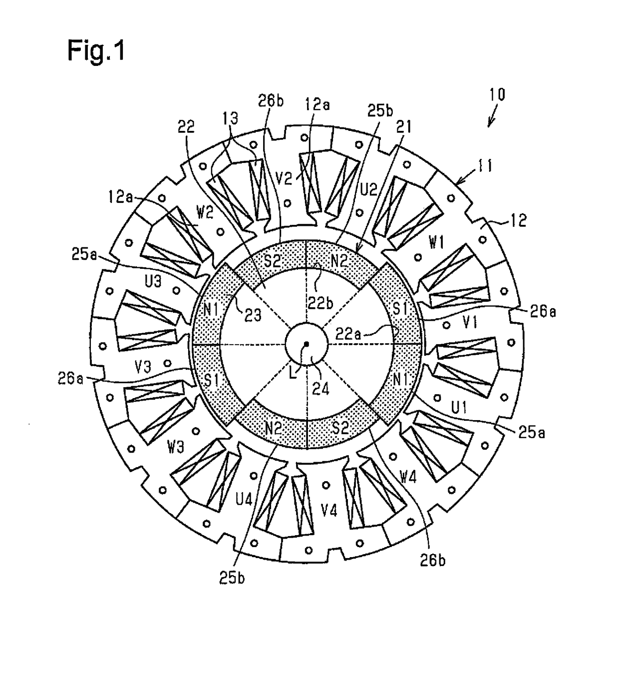
[0055]As shown in FIG. 1, a motor 10 according to the present embodiment is configured as a brushless motor and includes an annular stator 11 and a rotor 21 arranged at an inner side of the stator 11.

[0056]Structure of Stator

[0057]The stator 11 includes a stator core 12 and windings 13 wound around the stator core 12. The stator core 12 is substantially ring-shaped and formed from a magnetic metal. The stator core 12 includes twelve teeth 12a extending inward in the radial direction at equal angular intervals in the circumferential direction.

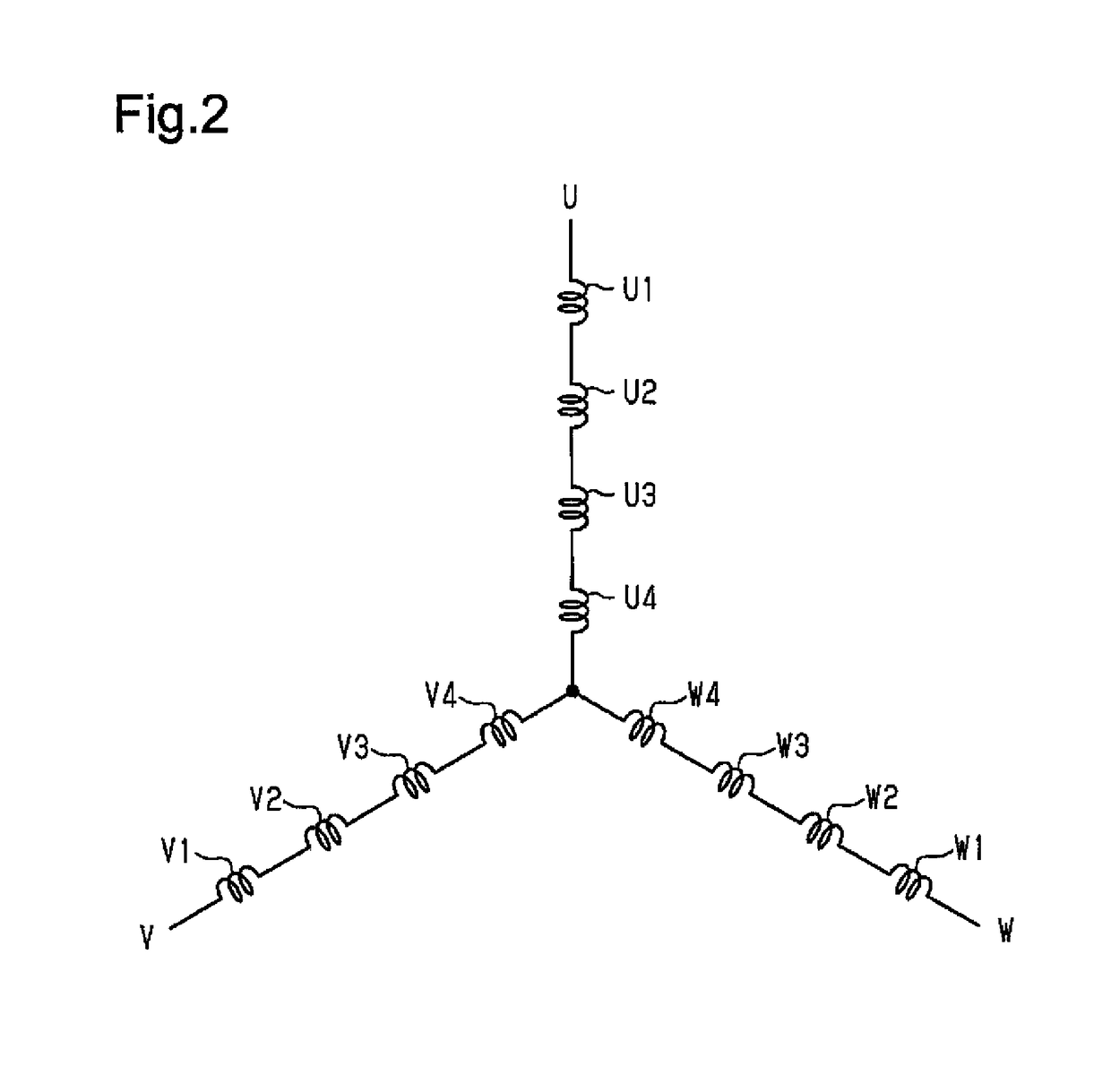
[0058]There are twelve windings 13, the number of which is the same as the teeth 12a. The windings 13 are wound as concentrated windings in the same direction around the teeth 12a, respectively. That is, the twelve windings 13 are arranged in the circumferential direction at equal angular intervals (thirty-degree intervals). The windings 13 are classified into three phases in accordance with the supplied drive...

second embodiment

[0124]a motor will now be described.

[0125]As shown in FIG. 10, a motor 110 according to the present embodiment is configured as a brushless motor in which a rotor 121 is arranged inside an annular stator 11. The configuration of the stator 11 is identical to that of the stator 11 according to the first embodiment, and thus detailed descriptions thereof are omitted. The configuration of windings 13 of the stator 11 is also identical to that of the windings 13 according to the first embodiment shown in FIG. 2.

[0126]Structure of Rotor

[0127]As shown in FIGS. 10, 11, and 12, the rotor 121 includes a rotation shaft 122, paired rotor cores 123n and 123s with the same shape, and a permanent magnet 124 arranged between the paired rotor cores 123n and 123s in the axial direction. The rotor cores 123n and 123s are made of a magnetic metal. In the following description, a rotor core that abuts against an N-pole-side end surface of the axially magnetized permanent magnet 124 is referred to as th...

third embodiment

[0212]a motor will now be described.

[0213]As shown in FIG. 21A, a motor 210 according to the present embodiment is configured as a brushless motor in which a rotor 221 is arranged inside an annular stator 11. The configuration of the stator 11 is identical to that of the stator 11 according to the first embodiment, and thus detailed descriptions thereof are omitted. The configuration of windings 13 of the stator 11 is also identical to that of the windings 13 according to the first embodiment shown in FIG. 2.

[0214]Structure of Rotor

[0215]As shown in FIG. 21B, the rotor 221 includes a rotor core 222 and permanent magnets 223. The rotor core 222 is made of a magnetic metal in a substantially disc shape, and a rotation shaft 224 is fixed to the center portion. Two magnet fixing portions 225 and four projections 226 are formed on the outer circumferential part of the rotor core 222.

[0216]The magnet fixing portions 225 are opposed to each other at 180° in the circumferential direction. T...


PUM


Abstract

A motor includes a stator having a winding, and a rotor. The rotor rotates by receiving a rotational magnetic field generated by drive current supplied to the winding. The winding includes a first winding and a second winding, the first and second windings both being excited at the same timing by the drive current. The first winding and the second winding are connected in series. The rotor includes a first pole section and a second pole section. The second pole section faces the second winding at the rotation position of the rotor at which the first pole section faces the first winding. The magnetic force exerted on the stator by the second pole section is weaker than that exerted by the first pole section.

Description

TECHNICAL FIELD[0001]The present invention relates to a motor.BACKGROUND ART[0002]In the prior art, as described in, for example, patent document 1, a permanent magnet motor such as a brushless motor includes a stator, which is formed by windings wound around a stator core, and a rotor, which uses permanent magnets opposing the stator, as poles. The windings of the stator are supplied with drive currents to generate a rotational magnetic field that rotates the rotor.PATENT DOCUMENT[0003]Patent Document 1: Japanese Laid-Open Patent Publication No. 2014-135852SUMMARY OF THE INVENTIONProblems that are to be Solved by the Invention[0004]In a permanent magnet motor such as that described above, when the rotor is driven to rotate at a higher speed, an increase in flux linkage resulting from the permanent magnets of the rotor increases the induced voltage at the windings of the stator. The induced voltage lowers the motor output and hinders rotation of the rotor at a higher speed. If the m...

Claims


Application Information

Patent Timeline
Patent Type & Authority Applications(United States)
IPC IPC(8): H02K1/27H02K1/24
CPCH02K1/276H02K1/24H02P25/024H02K1/278H02K1/148H02K1/185H02K15/14H02K21/16H02K1/2706H02K1/2713H02K1/272H02K1/2773H02K3/28H02K2213/03H02P2207/05H02K1/2781
Inventor YAMADA, YOJIMIKAMI, KOJIHATTORI, AKIHISAYOKOYAMA, SEIYA
Owner DENSO CORP
Why Eureka
Try Eureka