Welding wire feeder device

Active Publication Date: 2019-02-07
ESAB AB
View PDF1 Cites 3 Cited by
  • Summary
  • Abstract
  • Description
  • Claims
  • Application Information

AI Technical Summary

Benefits of technology

The invention relates to a device for positioning and holding a welding wire in a way that prevents it from being distorted or compressed during welding. The device includes two gripper members that hold the wire in a parallel relationship to its movement path. The gripper members have projections with curved surfaces that contact the wire at different points along its length, reducing potential damage. The gripper members are made from a flexible material and are biased to a closed position. The device also includes a roller chain with individual linkages that provide increased contact area with the wire, allowing for smooth movement during welding.

Problems solved by technology

In addition, the user often needs to change the rollers and wire guides when switching between welding wires of different diameters.
In addition to the time it takes to switch the rollers / guides, this also introduces the possibility that the user may use the wrong set of rollers and / or guides.
The user may also need to adjust the pressure of the feed rollers, which introduces the possibility that the user may incorrectly set the roller pressure, resulting in an undesirably high degree of wire deformation due to the high pressure.
In addition, the mechanism may become clogged as a result of a peeled wire caused by too much pressure and / or nonalignment in the mechanism, and unreliable feeding of the wire due to wire slippage (contact point friction).
Further, safety issues (e.g., finger pinching and the like) may be a concern as a user accesses and opens the mechanism.
Furthermore, prior art wire feeders that rely on a pair of rotating rollers generally require a high level of maintenance, which results in high maintenance costs associated with buying and stocking spare parts, and which increases the potential for improper maintenance practices.
Unfortunately, adding a second pair of rollers often creates new issues.
For example, with the introduction of a second pair of rollers, an increased risk exists for tangling of the wire, especially between the two pairs of rotating rollers.
Also there is an increased risk of “shaving,” which is the tearing-away of material from the surface of the wire due to misalignment between the grooves formed in the rotating rollers and associated nozzles, and due to slipping of the wire relative to the rotating rollers.
This can increase the possibility of clogging of the feed mechanism, the torch cable liner, and the torch.

Method used


Image

  • Welding wire feeder device
  • Welding wire feeder device
  • Welding wire feeder device

Examples


Embodiment Construction

[0027]A device in accordance with the present disclosure will now be described more fully hereinafter with reference to the accompanying drawings, in which preferred embodiments of the device are shown. The disclosed device, however, may be embodied in many different forms and should not be construed as being limited to the embodiments set forth herein. Rather, these embodiments are provided so that this disclosure will be thorough and complete, and will fully convey the scope of the device to those skilled in the art. In the drawings, like numbers refer to like elements throughout.

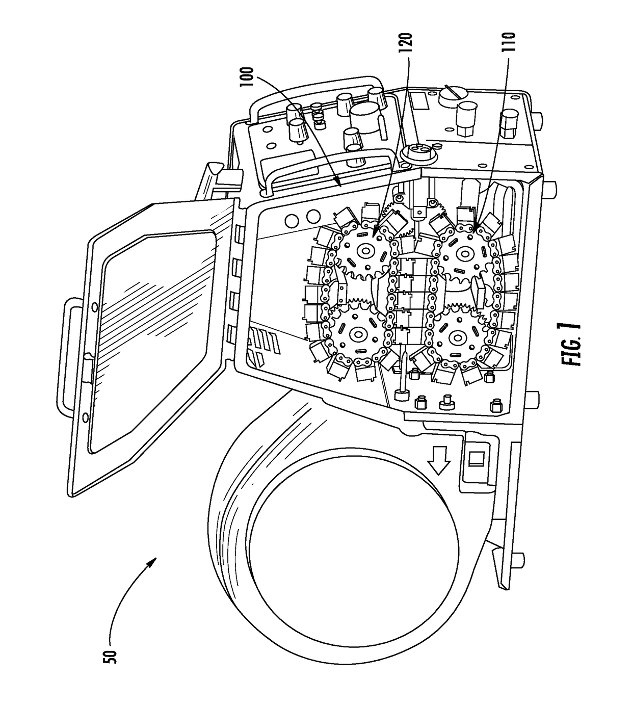
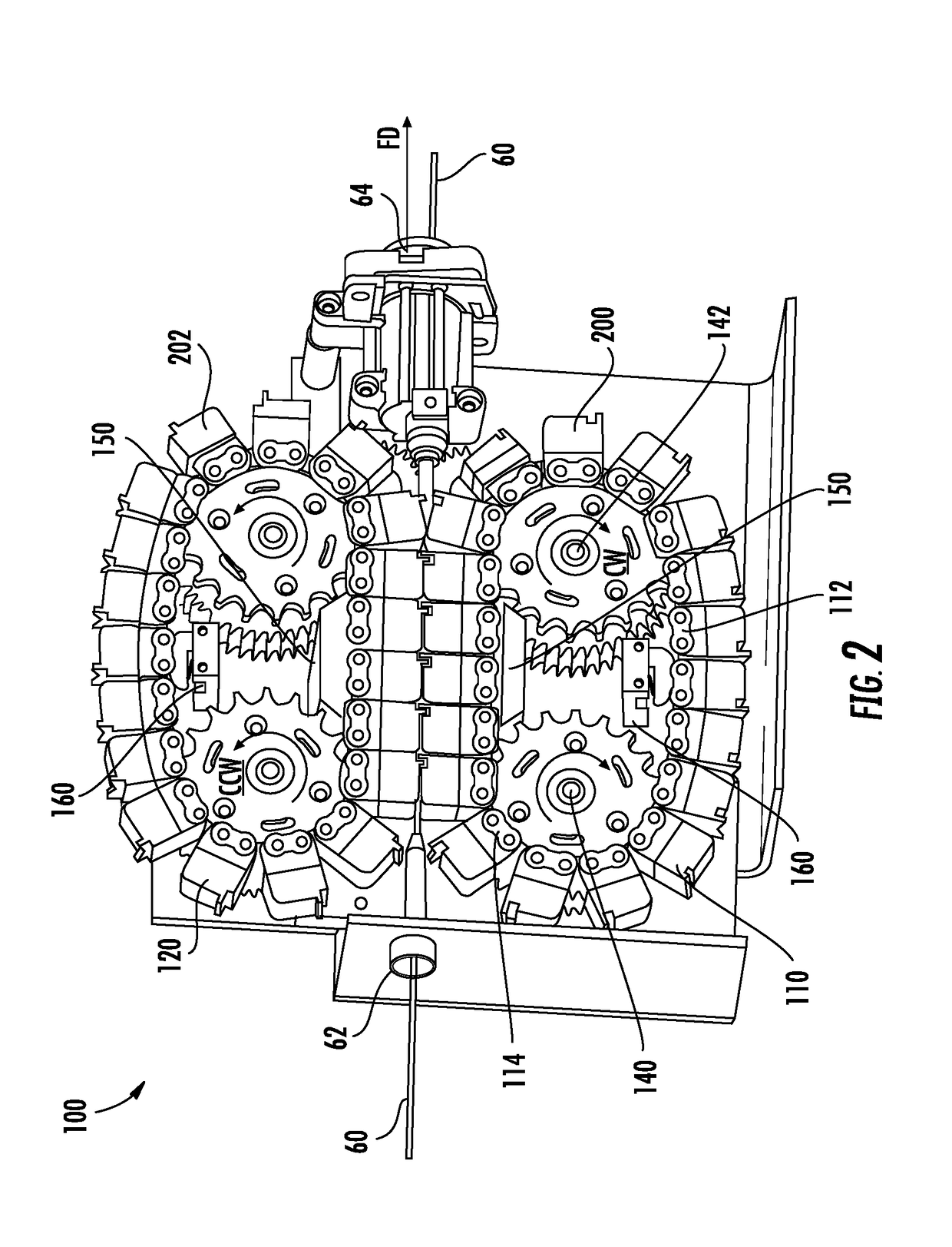
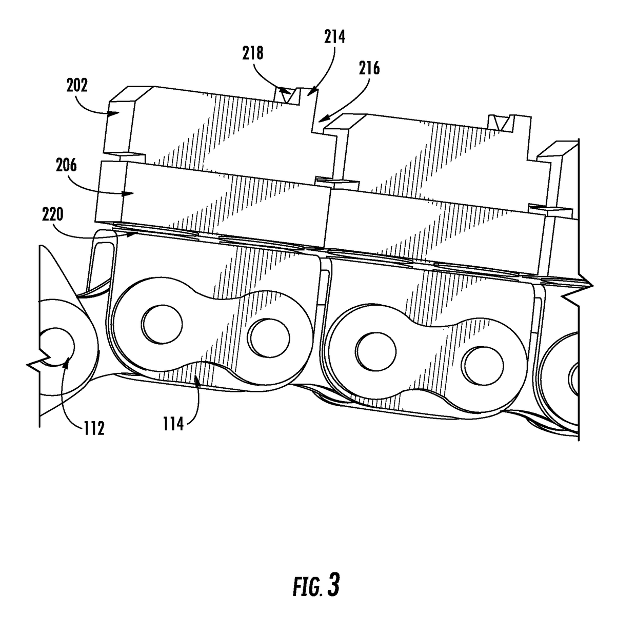
[0028]Referring to FIGS. 1-4D, an exemplary embodiment of a welding device 50 incorporating a wire feeder device 100 for contacting and feeding a welding wire 60 (shown in FIG. 2) in accordance with the present disclosure is shown. While the present disclosure is illustrated and described in terms of feeding a welding wire in a welding device, it is contemplated that the present disclosure has applicabili...


PUM

PropertyMeasurementUnit
Forceaaaaaaaaaa
Lengthaaaaaaaaaa
Sizeaaaaaaaaaa

Abstract

A wire feeder device for feeding a welding wire in a feeding direction is disclosed. The wire feeder device includes one or more roller chains and a plurality of first and second gripper members. The gripper members are movable from an open position to a closed position to contact and grip the welding wire. In use, the first and second gripper members are longitudinally movable with the roller chain(s) so that the welding wire is pulled along a substantially linear path. The first and second gripper members may be orientated in a vertical (i.e., coplanar) orientation or a horizontal, lateral orientation. The gripper members may include a built-in centering function to center a position of the welding wire.

Description

FIELD OF THE DISCLOSURE[0001]Embodiments of the present disclosure relate generally to welding wire feeders, and in particular, to a caterpillar style wire feeder.BACKGROUND OF THE DISCLOSURE[0002]Welding is a widely known process. Generally speaking, welding may be performed manually or, in some applications, it may be automated. Welding operations rely on a variety of types of equipment to ensure the supply of welding consumables (e.g., wire feed, shielding gas, etc.) is provided to the weld joint in an appropriate amount at the desired time. For example, a wire feeder is often used to provide welding wire at a desired feed rate to a welding torch.[0003]Wire feeders facilitate the feeding of welding wire from a wire spool or drum to a welding torch at a desired wire feed rate. In general, prior art wire feeders incorporate at least one pair of rotating wire feed rollers to feed the wire. In these systems, the needed pulling friction between the rollers and the wire may be created ...

Claims


Application Information

Patent Timeline
IPC IPC(8): B23K9/133
CPCB23K9/1336
Inventor VESANEN, JORMA KALEVI
Owner ESAB AB
Why Eureka
Try Eureka