
Color filter and display panel

Inactive Publication Date: 2019-02-07
TCL CHINA STAR OPTOELECTRONICS TECH CO LTD
View PDF5 Cites 1 Cited by
  • Summary
  • Abstract
  • Description
  • Claims
  • Application Information

AI Technical Summary

Benefits of technology

This patent aims to improve the quality of display panels by improving the diffusion uniformity of an alignment film. By setting the opening of photoresist layer in the overlapping region on the non-display and longitudinal light filtering region of the color filter unit, the surface flatness of the color filter is increased, resulting in better alignment film diffusion and higher quality display panels. The technical problem of poor display quality due to poor alignment film diffusion in previous color filter and display panels is solved.

Problems solved by technology

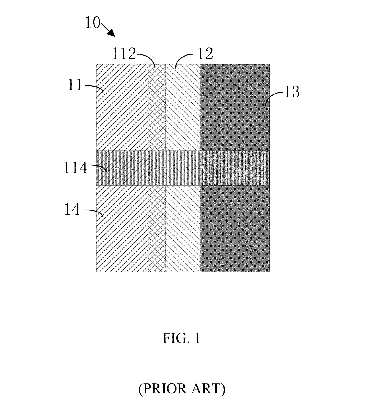
In existing display panels, an overlapping region of the lateral light shielding region and the longitudinal light shielding region is provided with the color filter and the black matrix of two sub-pixel units, a height of the overlapping region is thus greater than that of other regions, which affects surface flatness of the display panel, thereby affecting diffusion uniformity of an alignment film in an alignment film process, and affecting quality of the display panel.

Method used


Image

  • Color filter and display panel
  • Color filter and display panel
  • Color filter and display panel

Examples


Embodiment Construction

[0052]The following clearly and completely describes the technical solutions in the embodiments of the present disclosure with reference to the accompanying drawings in the embodiments of the present disclosure. Apparently, the embodiments to be described are merely part rather than all of the embodiments of the present disclosure. All other embodiments obtained by persons of ordinary skill in the art based on the embodiments of the present disclosure without creative efforts shall fall within the protection scope of the present disclosure.

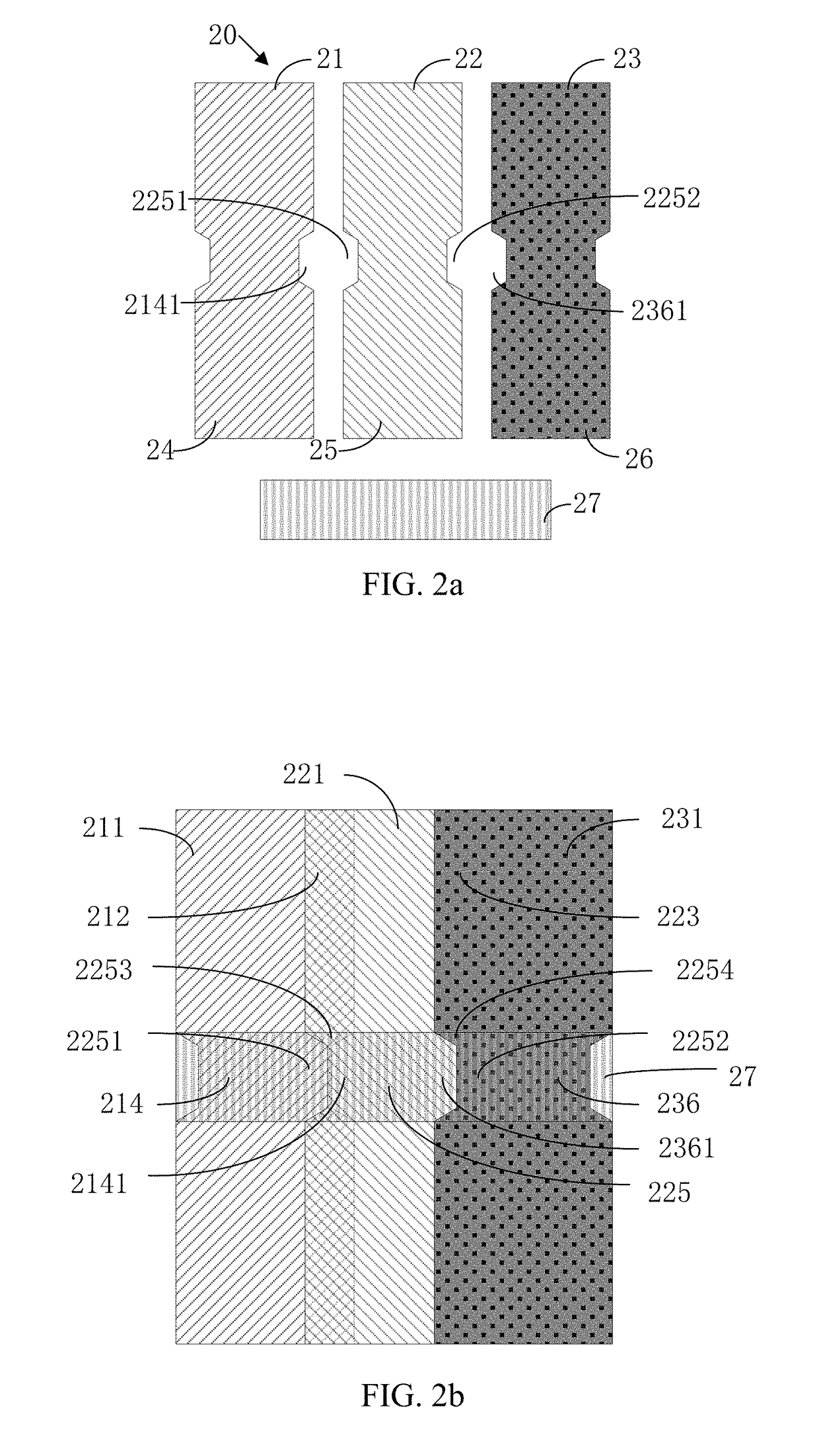
[0053]Refer to FIG. 2a and FIG. 2b, where FIG. 2a is an exploded diagram of a color filter of a display panel of a first preferred embodiment of the present disclosure, and FIG. 2b is a structural diagram of the color filter of the display panel of the first preferred embodiment of the present disclosure. A color filter 20 of the present disclosure includes a plurality of color filter units arranged in an array, where two laterally adjacent color ...


PUM


Abstract

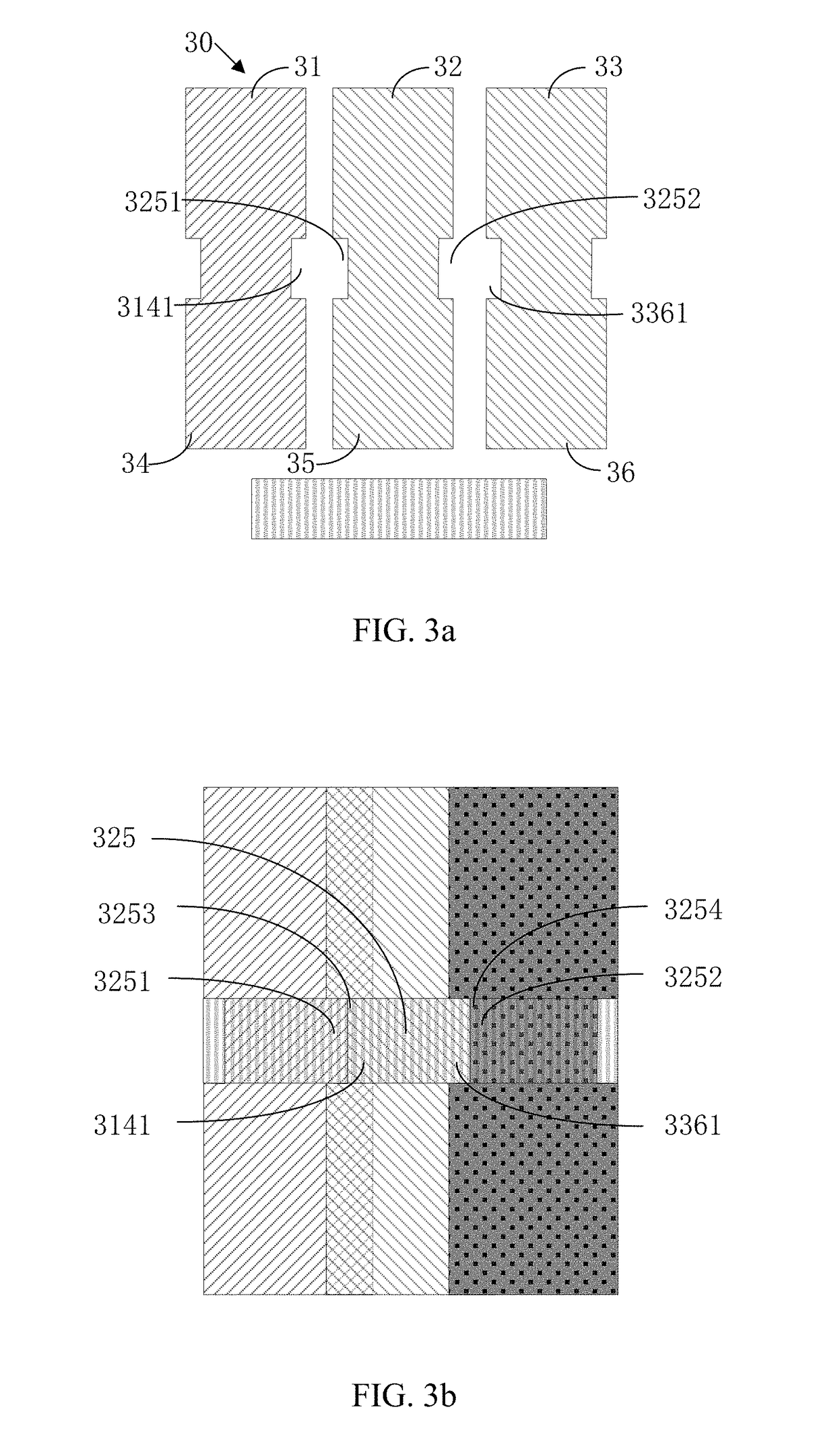
A color filter is provided, which includes a plurality of color filter units arranged in an array. Each color filter unit includes a display and light filtering region, a non-display and lateral light shielding region, and a non-display and longitudinal light shielding region, where an opening of photoresist layer in the overlapping region is formed on at least one side of the non-display and longitudinal light filtering region of the color filter unit for decreasing an area of the non-display and longitudinal light shielding region of two color-filter photoresist layers. A display panel is also provided.

Description

FIELD OF DISCLOSURE[0001]The present disclosure relates to the field of displays, and more particularly to a color filter and a display panel.BACKGROUND[0002]With development of display panel technology, users have higher requirements for display panels. As resolution of display panels increases, size of pixel units of the display panels is decreasing.[0003]FIG. 1 is a structural diagram of a color filter of a display panel in the prior art. The display panel includes a red sub-pixel unit, a blue sub-pixel unit, and a green sub-pixel unit. The color filter 10 includes a red color filter unit 11 corresponding to the red sub-pixel unit, a blue color filter unit 12 corresponding to the blue sub-pixel unit, and a green color filter unit 13 corresponding to the green sub-pixel unit. Due to different colors of adjacent sub-pixel units in a horizontal direction, an overlapping region of two color filters can be set in an intersection area of the sub-pixel units to form a lateral light shie...

Claims


Application Information

Patent Timeline
IPC IPC(8): G02F1/1335
CPCG02F1/133514G02F1/133512G02F1/1337G02F2201/52G02F1/133516G02F1/133519
Inventor LIU, ZHONGJIE
Owner TCL CHINA STAR OPTOELECTRONICS TECH CO LTD
Learn More