
Method and apparatus for transmitting and receiving downlink control information in wireless communication system

Active Publication Date: 2019-02-07
SAMSUNG ELECTRONICS CO LTD
View PDF14 Cites 25 Cited by
  • Summary
  • Abstract
  • Description
  • Claims
  • Application Information

AI Technical Summary

Benefits of technology

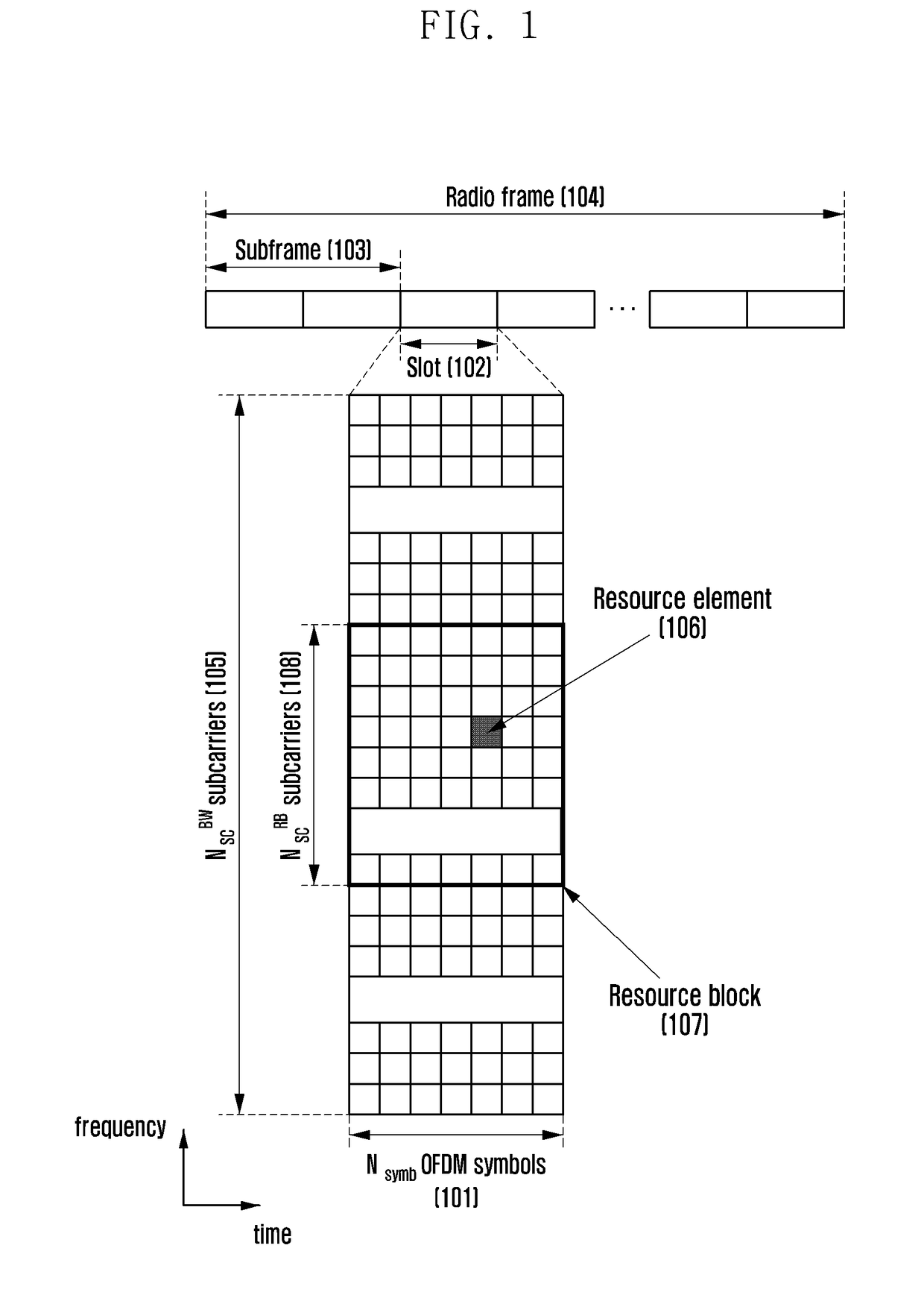
The patent text discusses a method for improving the flexibility of the control resource set in a wireless communication system, which can be configured over specific subbands and have different lengths in the time domain. This allows for efficient management of the control region based on the requirements of different services. Additionally, the text describes a low power monitoring scheme for the downlink control channel, which reduces the number of blind decodings and improves energy efficiency in the terminal.

Problems solved by technology

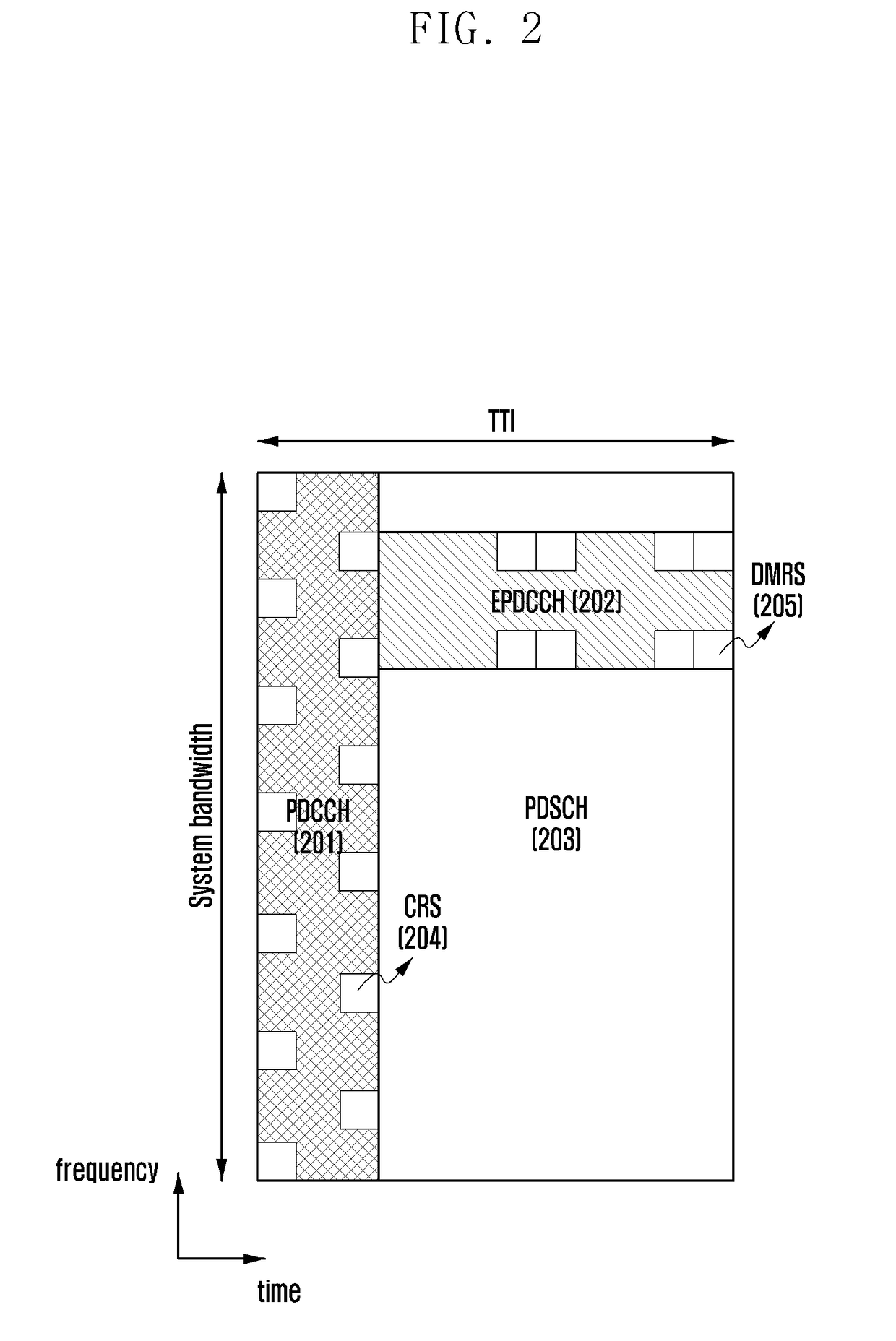
The PDCCH used in the current LTE system may be not suitable for ensuring flexibility because it is transmitted over the entire bandwidth and the size of the control region is cell-specific.

Method used


Image

  • Method and apparatus for transmitting and receiving downlink control information in wireless communication system
  • Method and apparatus for transmitting and receiving downlink control information in wireless communication system
  • Method and apparatus for transmitting and receiving downlink control information in wireless communication system

Examples


second embodiment

[0140]Upon determining that the frequency domain resource to which the PDSCH is to be allocated overlaps with the control region, at operation 903, the base station may determine whether to reuse the resource in the control region for PDSCH transmission. In the second embodiment, the base station can determine this based on the overlap ratio between the PDSCH to be transmitted and the search space (it can also be determined based on the non-overlap ratio). If the overlap ratio is greater than the preset threshold (η), at operation 904, the base station may determine not to reuse the resource in the control region for PDSCH transmission. At operation 906, the base station may determine the time domain resource allocation of the PDSCH correspondingly. That is, the time domain resource allocation for the PDSCH can be started from the OFDM symbol not included in the control region. Conversely, if the overlap ratio is less than the preset threshold (η), at operation 905, the base station...

third embodiment

[0150]In the third embodiment, to map the DCI to specific PDCCH candidates for transmission, the base station may determine the resource allocation for DCI transmission differently according to the DCI format. More specifically, for the DCI format corresponding to the downlink scheduling assignment, the base station can map the corresponding DCI to specific PDCCH candidates (i.e., candidates selected from the PDCCH candidates reused for PDSCH transmission in the search space) in the total search space. For other DCI formats, the base station can map the corresponding DCI to specific PDCCH candidates (i.e., candidates selected from the PDCCH candidates not reused for PDSCH transmission in the search space) in the remaining search space not reused for PDSCH transmission. For example, in FIG. 10, the base station can map DCI #1 (1004) corresponding to the downlink scheduling assignment to one PDCCH candidate 1006 in the total search space 1001 for transmission. The base station may map...


PUM


Abstract

The disclosure relates to a communication method and system for converging a 5th-generation (5G) communication system for supporting higher data rates beyond a 4th-generation (4G) system with a technology for internet of things (IoT). The disclosure may be applied to intelligent services based on the 5G communication technology and the IoT-related technology, such as smart home, smart building, smart city, smart car, connected car, health care, digital education, smart retail, security and safety services. A method and apparatus that reduce power consumption of the terminal and increase resource utilization efficiency of the base station through resource sharing between the data channel and the control channel are provided.

Description

CROSS-REFERENCE TO RELATED APPLICATION(S)[0001]This application is based on and claims priority under 35 U.S.C. § 119 of a Korean patent application number 10-2017-0099030, filed on Aug. 4, 2017, in the Korean Intellectual Property Office, the disclosure of which is incorporated by reference herein in its entirety.BACKGROUND1. Field[0002]The disclosure relates to a wireless communication system. More particularly, the disclosure relates to a method and apparatus for transmitting and receiving downlink control information (DCI).2. Description of the Related Art[0003]To meet the demand for wireless data traffic, which has increased since deployment of 4th generation (4G) communication systems, efforts have been made to develop an improved 5th generation (5G) or pre-5G communication system. Therefore, the 5G or pre-5G communication system is also called a ‘Beyond 4G Network’ or a ‘Post long term evolution (LTE) System’. The 5G communication system is considered to be implemented in hig...

Claims


Application Information

Patent Timeline
IPC IPC(8): H04L1/00H04W72/04H04L5/00
CPCH04L1/0038H04L1/0061H04W72/042H04L5/0053H04W72/0446H04W72/0453H04L5/0007H04W52/0209H04L5/0044H04L5/0094Y02D30/70H04W72/20H04W72/1273H04W72/23H04L1/00
Inventor KIM, TAEHYOUNGKIM, YOUNGBUMYEO, JEONGHOCHOI, SEUNGHOON
Owner SAMSUNG ELECTRONICS CO LTD
Learn More