Light converging system and transmission liquid crystal display

Inactive Publication Date: 2005-08-18
NITTO DENKO CORP
View PDF7 Cites 19 Cited by
  • Summary
  • Abstract
  • Description
  • Claims
  • Application Information

AI Technical Summary

Benefits of technology

[0065] In a light condensing system of the present invention, first light condensation to be required in the first light condensing section (X) is within ±60° and desirably within ±50°. This is because secondary transmission of a light condensing film used as the second light condensing element (Y) is observed generally in the range of from 60 to 70° as shown in FIG. 21. By combining with a light source generating substantially no emitted light at an angle at which the secondary transmission component is generated, the secondary transmission can be effectively shielded to thereby efficiently reuse required light outgoing to outside a display viewing angle range in essence because of secondary transmission. Note that a graph shown in FIG. 21 is a measurement result of a light condensa

Problems solved by technology

This is a high level that cannot be acquired by a conventional backlight system with a prism sheet or microdot array alone.
In a case where a shield wavelength bandwidth is narrow, problems have occurred that a secondary transmission occurs in an oblique direction which results in light passing-through in an oblique direction only to be wasteful and, in addition, that coloring occurs because transmittance is different according to a wavelength.
For example, in a case of a bright line type light condensing element in which a band pass filter and a bright line light source are combined, a necessary bright line is transmitted only through the front but shield in an oblique direction, whereas since three transmission wavelengths are available, there has arisen a problem that with a large incidence angle, a region transmitting green light in the front shifts up to a blue bright-line region and thereby transmits blue light.
There has further arisen a problem that a region transmitting red light shifts up to a green bright line region and thereby transmits green light.
All of the patent literatures, however, limit its description only to an effect of the vicinity of the front but have given no solution to a problem of secondary transmission at a large incidence angle.
With a large

Method used


Image

  • Light converging system and transmission liquid crystal display
  • Light converging system and transmission liquid crystal display
  • Light converging system and transmission liquid crystal display

Examples


Example

Example 1

(Preparation of Second Light Condensing Element (Y))

[0284] Used as a second light condensing element (Y) was an evaporation-deposited multilayer film band pass filter with 15 TiO2 / SiO2 layers. A polyethylene terephthalate film with a thickness of 50 μm was used as a base material and a total thickness was about 53 μm. A design table including thickness of layers of the evaporation-deposited thin film is shown in Table 1 described blow. TABLE 1LayersmaterialLayer thickness (nm)15TiO292.114SiO2130.113TiO268.312SiO297.211TiO263.210SiO288.29TiO2152.18SiO292.87TiO270.76SiO250.35TiO2148.64SiO295.83TiO265.52SiO296.91TiO265.3

(Light Source)

[0285] Used as a bright line light source (L) was a 10.4 inch type backlight (manufactured by Stanley Electric Co., Ltd.) using a side light type light guide (the light guide was of a wedged type in section and dot printing was applied on the back surface thereof). A three wavelength type cold cathode fluorescent lamp was used as a light sou...

Example

Example 2

(Preparation of Second Light Condensing Element (Y))

[0293] Used as the second light condensing element (Y) was a cholesteric liquid crystal band pass filter prepared by thin film coating of a cholesteric liquid crystal polymer. This is a combination of a right circularly polarized light reflecting band pass filter adapted for three wavelengths and a left circularly polarized light reflecting band pass filter adapted for three-wavelengths, and only the lights having three wavelength that are objects, are transmitted through in directions in the vicinity of the vertical direction and an incident light incoming in an oblique direction is reflected.

[0294] In the cholesteric liquid crystal band pass filter, the front transmission light is unpolarized light. This is because the liquid crystal layer is used as a band pass filter and transmission light from a region, where polarization separation caused by cholesteric reflection is not affected, transmits in the front direction...

Example

Example 3

(Preparation of Second Light Condensing Element (Y))

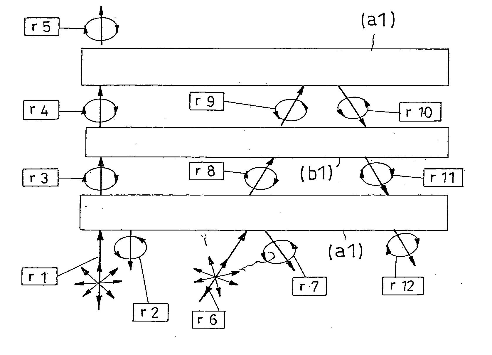
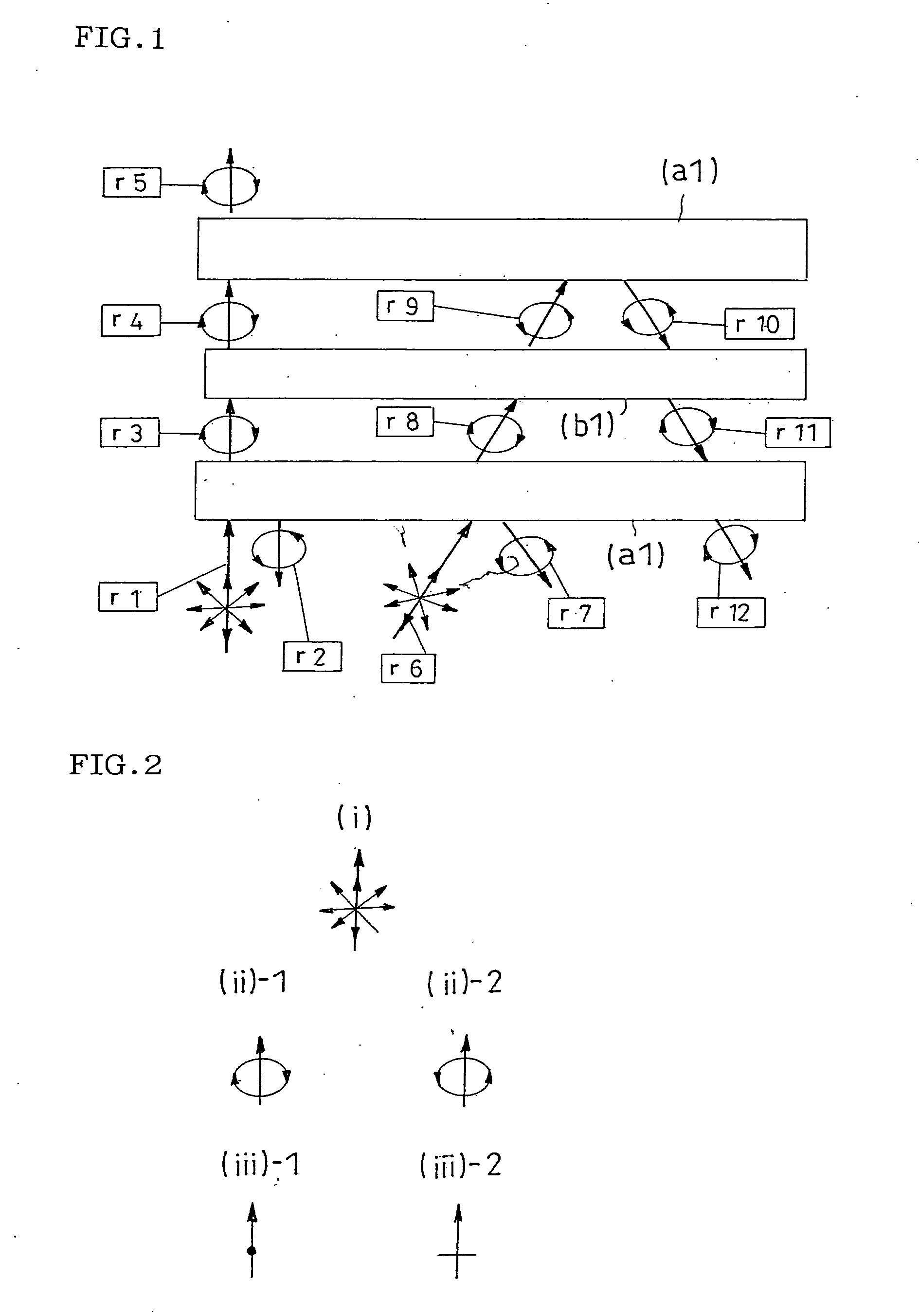
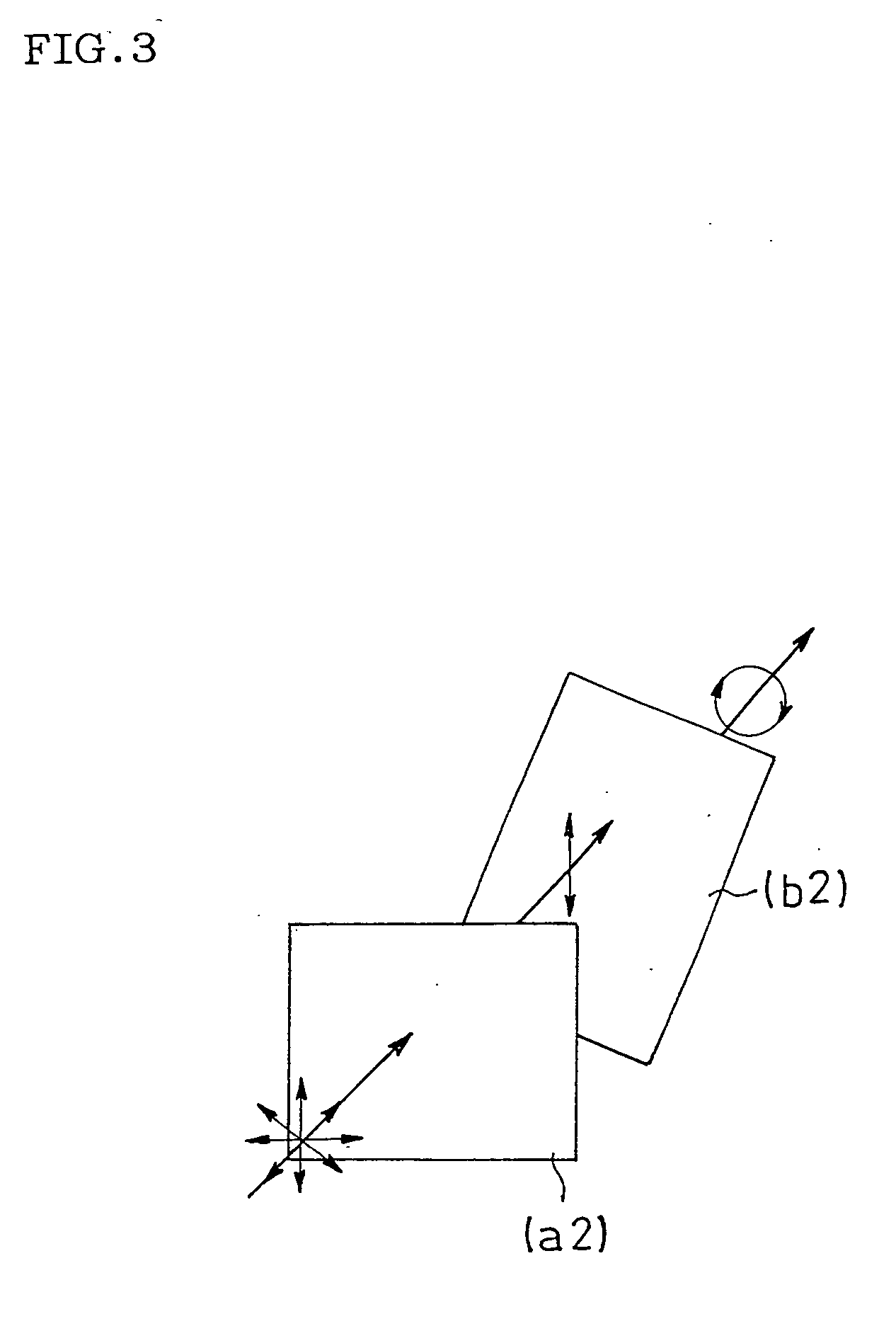
[0306] Used was as a second light condensing element (Y) was a polarization element obtained by providing a retardation plate (b1) between two circular polarization type reflection polarizer (a1) having respective polarized light selective reflection wavelength bands superimposed on each other.

[0307] Used as the circular polarization type reflection polarizers (a1) were cholesteric liquid crystal layers of NIPOCS film (PCF400) manufactured by NITTO DENKO CORP.

[0308] Then, the retardation plate (b1, a negative C plate) generating a front retardation of almost 0 and a retardation in an oblique direction was prepared with a polymerizable liquid crystal according the following method. LC242 manufactured by BASF Corp. was used as a polymerizable mesogen compound and LC756 manufactured by BASF Corp. was used as a polymerizable chiral agent. The polymerizable mesogen compound and the polymerizable chiral compound were used a...


PUM


Abstract

A light condensing system of this invention comprising: a backlight system having a light source and a first light condensing section (X) capable of condensing emitted light from the light source within ±60° of the front direction; and a light condensing film with no patterned structure as a second light condensing element (Y). The light condensing system effectively shield light passing-through in an oblique direction to thereby suppress uncomfortable coloring, present a good display, realize cost reduction.

Description

TECHNICAL FIELD [0001] The present invention relates to a light condensing system and a transmission liquid crystal display. BACKGROUND ART [0002] There has been known a technique in which lights from a diffusion light source are condensed in the front direction employing an evaporation band pass filter using a Brewstars angle (for example, see the specification of GP No. 3836995 A), or an optical film having an angle dependency with respect to a transmittance and a reflectance, such as a selective reflection characteristic of a cholesteric liquid crystal using Bragg reflection (for example, see publications of JP-A Nos. 2-158289, 6-235900, 10-321025 and the like). With such optical films employed, a filter can be manufactured that alters a reflectance according to an incidence angle and that transmits light only through the front thereof in a proper optical design. Light that cannot be transmitted therethrough is not absorbed but reflected thereon returns back to the light source s...

Claims


Application Information

Patent Timeline
IPC IPC(8): G02F1/13357G02F1/13363
CPCG02F1/13362G02F2001/133607G02F1/133634G02F1/133607G02F1/1335G02B6/0001
Inventor HARA, KAZUTAKATAKAHASHI, NAOKIMIYATAKE, MINORU
Owner NITTO DENKO CORP
Why Eureka
Try Eureka