Heating cooker

a technology for cookers and insulators, applied in the field of heating cookers, can solve the problems of reducing the life of heaters and micas, reducing the speed of heating an object to be heated, and excessive heating of inner heaters, so as to shorten the cooking period, suppress internal distortion of insulators, and high reliability

Active Publication Date: 2019-02-07
PANASONIC INTELLECTUAL PROPERTY MANAGEMENT CO LTD
View PDF5 Cites 12 Cited by
  • Summary
  • Abstract
  • Description
  • Claims
  • Application Information

AI Technical Summary

Benefits of technology

[0010]The present invention provides a heating cooker that is highly reliable and achieves shortening of a cooking period by suppressing internal distortion of an insulator caused by heating of a planar heater.
[0011]A heating cooker of the present invention includes a heating chamber in which an object to be heated is contained, a heater having a planar shape and disposed on an outer side of an upper surface of the heating chamber, and a pressing unit that presses the heater onto the upper surface of the heating chamber. Furthermore, the heater includes a continuous plane-shaped insulator, a planar heat generator provided in the insulator, and a distortion suppressor that suppresses internal distortion of the insulator that occurs due to heating of the planar heat generator.
[0012]Since the heater includes the distortion suppressor that suppresses internal distortion of the insulator, deformation is suppressed even in a case where the insulator is heated by the planar heat generator. This keeps contact between the planar heat generator and the insulator and contact between the heating chamber upper surface and the heater. Since heat transfer from the planar heat generator to the upper surface of the heating chamber is thus kept good, the planar heat generator is not excessively heated, and therefore it is possible to prolong lifetime of the planar heat generator and the insulator.
[0013]Furthermore, good heat transfer between the planar heat generator and the upper surface of the heating chamber increases a heat rising speed of the upper surface of the heating chamber. This makes it possible to increase a heating speed of the object to be heated. Since heat efficiency is high, it is possible to complete cooking in a short period.

Problems solved by technology

This causes inner distortion due to a difference in thermal expansion between a heated portion and a non-heated portion, resulting in deformation.
This deteriorates heat transfer between inner heater 111 and lower mica plate 108, thereby leading to a possibility of excessive heating of inner heater 111.
This causes problems such as a decrease in lifetime of heater and mica and a decrease in speed of heating of an object to be heated.

Method used


Image

  • Heating cooker
  • Heating cooker
  • Heating cooker

Examples


first exemplary embodiment

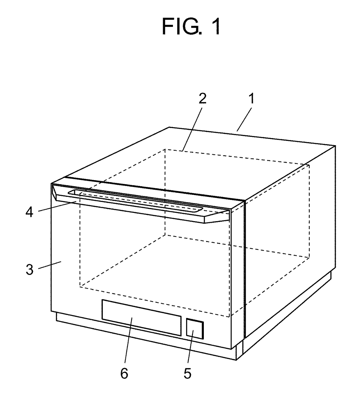
[0029]FIG. 1 is a perspective view illustrating external appearance of heating cooker 1 according to a first exemplary embodiment of the present invention.

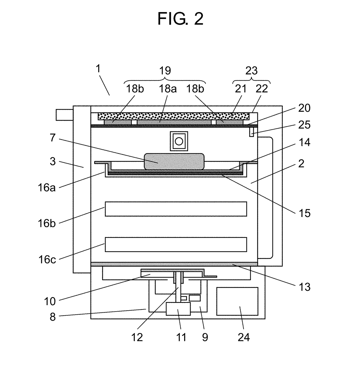
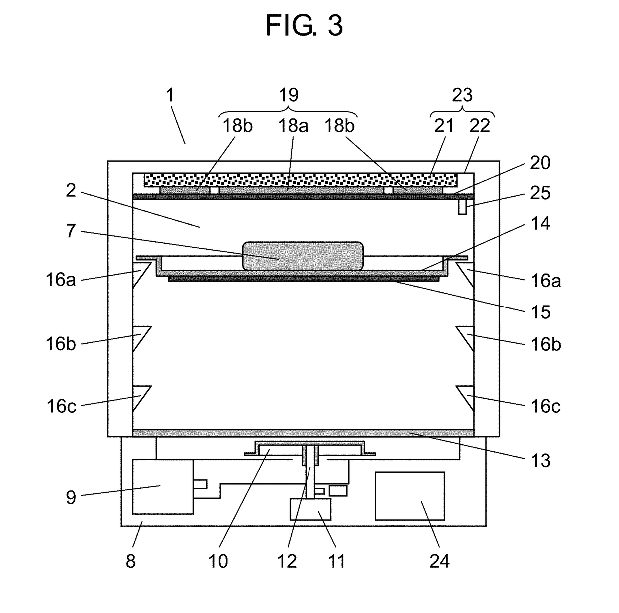
[0030]Heating cooker 1 according to the present exemplary embodiment heats object to be heated 7 by supplying at least one of a microwave and radiation heat to heating chamber 2 that is opened on a front side and in which object to be heated 7 (see FIG. 2) is contained, for example, like a microwave oven having a grill function.

[0031]In the present exemplary embodiment, it is assumed that a side on which the front opening of heating chamber 2 is located is referred to as front, a right-hand side of a user facing a rear side while standing at the front is referred to as right, and a left-hand side of the user facing the main body while standing at the front is referred to as left.

[0032]Heating chamber 2 is provided in a body of heating cooker 1. Door 3 with lighting window that opens and closes the opening of heating chamber 2 is p...

second exemplary embodiment

[0083]Next, a configuration of a heater of a heating cooker according to a second exemplary embodiment of the present invention is described in detail with reference to the drawings.

[0084]FIG. 7 is a schematic view of heater 50 (a second heater) of heating cooker 1 according to the second exemplary embodiment of the present invention viewed from above. In the present exemplary embodiment, constituent elements and functions that are similar to those in the first exemplary embodiment are given identical reference signs, and description of constituent elements similar to those in the first exemplary embodiment is omitted. A configuration of the whole heating cooker according to the present exemplary embodiment is similar to the configuration of heating cooker 1 illustrated in FIGS. 1 through 3, 5A, 5B, 6A, and 6B.

[0085]As illustrated in FIG. 7, heater 50 (the second heater) of the heating cooker according to the present exemplary embodiment is configured such that a metal foil such as ...

third exemplary embodiment

[0094]Next, a configuration of a heater of a heating cooker according to a third exemplary embodiment of the present invention is described in detail with reference to the drawings.

[0095]FIG. 8 is a schematic view of heater 60 (a second heater) of heating cooker 1 according to the third exemplary embodiment of the present invention viewed from above. In the present exemplary embodiment, constituent elements that are similar to those in the first exemplary embodiment and the second exemplary embodiment are given identical reference signs, and description of constituent elements similar to those in the first and second exemplary embodiments is omitted. A configuration of whole heating cooker 1 according to the present exemplary embodiment is similar to the configuration of heating cooker 1 illustrated in FIGS. 1 through 3, 5A, 5B, 6A, and 6B.

[0096]As illustrated in FIG. 8, heater 60 (the second heater) according to the present exemplary embodiment is configured such that a metal foil ...


PUM


Abstract

The heating cooker includes a first heater disposed below a tray to heat the tray, and second heater disposed over the tray to heat the tray. In addition, the heating cooker includes a controller that controls output of the first heater and switches energization of second heater in accordance with a kind of object to be heated and a quantity of object to be heated. Furthermore, second heater includes two plane-shaped insulators and a plurality of planar heat generators that are sandwiched between insulators, and the controller heats regions that are disposed over and below the tray to be opposed to each other by controlling energization of the first heater and second heater. Furthermore, second heater has a distortion suppressor between the plurality of planar heat generators, and the distortion suppressor suppresses internal distortion of insulators caused by heating of the plurality of planar heat generators of second heater.

Description

TECHNICAL FIELD[0001]The present invention relates to a heating cooker having a grill function of grilling a food item by using a planer heater so that the food item is browned.BACKGROUND ART[0002]Conventionally known as this kind of heating cooker is a heating cooker that heats an object to be heated from above and below or from above or below by using an upper surface heater that heats the object to be heated from above and a lower surface heater that heats the object to be heated from below (see, for example, Patent Literature 1).[0003]FIG. 11 is a schematic view illustrating a heating cooker disclosed in Patent Literature 1, and FIG. 12 is a schematic view illustrating a configuration of an upper surface heater of the heating cooker disclosed in Patent Literature 1. The configuration is described below with reference to FIGS. 11 and 12.[0004]Heating cooker 100 disclosed in Patent Literature 1 includes heating chamber 102 in which a food item that is object to be heated 101 is co...

Claims


Application Information

Patent Timeline
Patent Type & Authority Applications(United States)
IPC IPC(8): H05B6/68A47J37/06H05B6/64
CPCH05B6/687A47J37/0629H05B6/6482H05B6/6435F24C7/067F24C7/087H05B3/286H05B6/6402H05B6/6408H05B6/6491H05B6/725F24C7/046Y02B40/00
Inventor KUNIMOTO, KEIJIROUHOSOKAWA, DAISUKE
Owner PANASONIC INTELLECTUAL PROPERTY MANAGEMENT CO LTD
Why Eureka
Try Eureka