
Laser metal deposition head

a laser metal deposition and laser technology, applied in the field of improved laser metal deposition heads, can solve the problems of difficult maintenance of conventional lmd head designs, large diameter of existing designs, and inability to access tight spaces

Active Publication Date: 2019-02-14
FORMALLOY LLC
View PDF8 Cites 15 Cited by
  • Summary
  • Abstract
  • Description
  • Claims
  • Application Information

AI Technical Summary

Benefits of technology

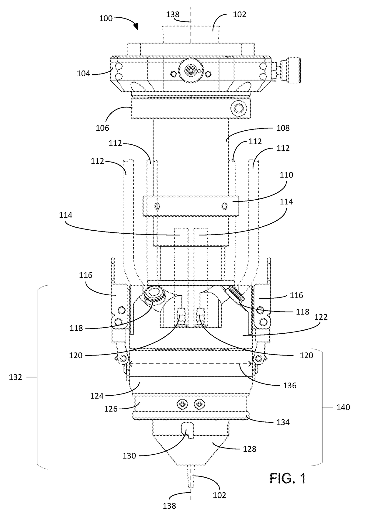
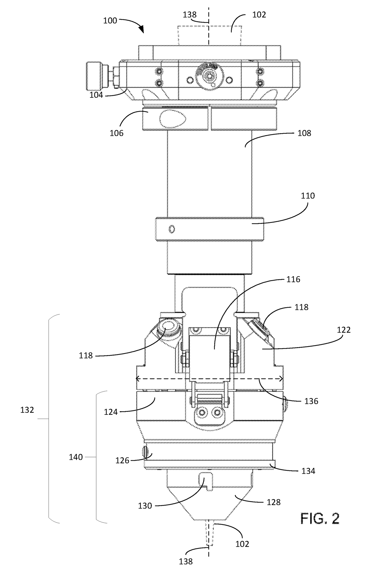
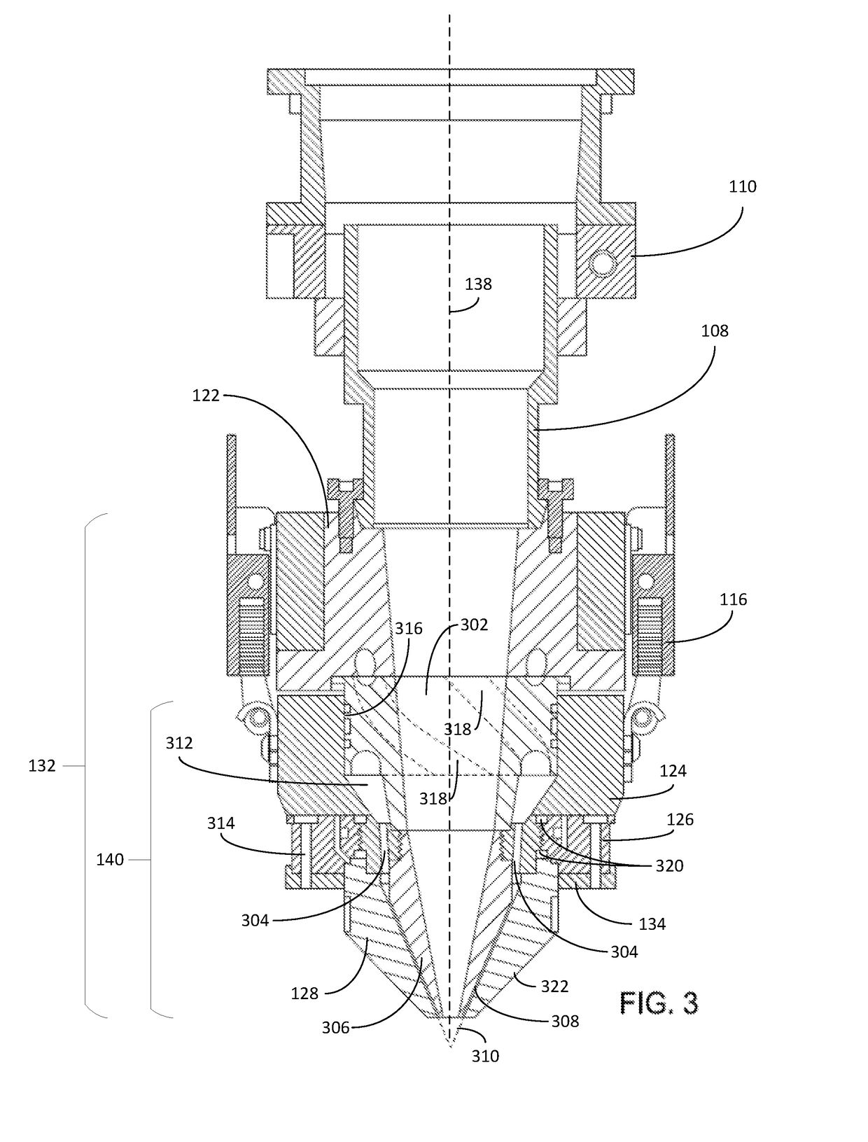
This patent text describes a laser metal deposition head that includes a main body with multiple powder inlets, powder flow channels, a shield gas inlet, and an auxiliary gas inlet. The head also has a nozzle seat with separate channels for shield gas, auxiliary gas, and powder distribution. The head has an inner nozzle and an outer nozzle that form a conical powder outlet channel. The head also has a powder flow guide and a coolant sleeve that is in contact with the outer nozzle's outer surface. The technical effects of this design include improved powder mixing and cooling, which can improve the quality and efficiency of laser metal deposition processes.

Problems solved by technology

Existing LMD head designs suffer from many design shortcomings.
For example, conventional LMD head designs are often difficult to maintain, requiring time-intensive disassembly to clean out powder and to change out nozzles.
Further, existing designs tend to be too large in diameter to access tight spaces, especially due to inlet and outlet hoses protruding from the body of the LMD head.
Such diameters are typically greater than 100 mm when accounting for the protrusion of the hoses, which may limit precision of builds due to the access limitations of a large LMD head.
Further, the large diameter and protrusions create susceptibility to laser reflections, which may damage the powder, gas, coolant delivery lines, and other parts of the LMD head.
As another example, conventional LMD head designs inefficiently deliver powder to the laser melt pool.
For example, LMD heads with independent powder-stream nozzles, such as those with three or more independent powder streams, typically cannot focus the powder into the laser spot as precisely or efficiently as a coaxial-type nozzle.
In some cases, the delivery rate may be less than 50%, which leads to wasted material and difficulty in controlling the deposition quality.
As yet another example, conventional LMD heads are generally not configured for easy nozzle changes.
Finally, existing designs do not allow for customization of auxiliary shield gas flows.

Method used


Image

  • Laser metal deposition head
  • Laser metal deposition head
  • Laser metal deposition head

Examples


example additive

Manufacturing System

[0086]FIG. 12 depicts an example of an additive manufacturing system 1200. Additive manufacturing system 1200 includes a user interface 1202. User interface 1202 may be, for example, a graphical user interface comprising hardware and software controls for controlling additive manufacturing system 1200. In some examples, user interface 1202 may be integral with additive manufacturing system 1200 while in other examples user interface 1202 may be remote from additive manufacturing system 1200 (e.g., on a remote computer such as a laptop computer or a personal electronic device).

[0087]Additive manufacturing system 1200 also includes a control system 1204. In this example, control system 1204 is in data communication with user interface 1202 as well as directed energy source 1206, material feed 1208, gas feed 1210, distance sensor 1214, process motion system 1212, tooling 1216, and build surface motion system 1224. In other examples, control system 1204 may be in dat...


PUM

PropertyMeasurementUnit
Angleaaaaaaaaaa
Angleaaaaaaaaaa

Abstract

Aspects of the present disclosure relate to improved laser metal deposition heads. Various embodiments may include a main body, a nozzle seat, a powder flow guide, an inner nozzle, an outer nozzle, and a coolant sleeve. In some embodiments, powder inlets in the main body are angled relative to a primary axis of the laser metal deposition head. In some embodiments, the nozzle seat includes a plurality of powder distribution channels that are also angled relative to the primary axis of the laser metal deposition head.

Description

CROSS-REFERENCE TO RELATED APPLICATION[0001]This application claims the benefit of U.S. Provisional Patent Application No. 62 / 543,268, filed on Aug. 9, 2017, the disclosure of which is incorporated herein by reference in its entirety.INTRODUCTION[0002]Aspects of the present disclosure relate to improved laser metal deposition heads. Laser metal deposition (LMD), sometime alternatively referred to as laser deposition welding, is a laser-based additive manufacturing process in which metal structures are built up on a substrate or metal layers and structures are applied to existing components (e.g., cladding) in layers. In LMD, a laser generates a molten bath on an existing surface into which metal powder is directed through a nozzle in a deposition head (e.g., using a carrier gas). The powder melts and bonds with the base material in the molten pool thereby forming new layers and ultimately structures additively.[0003]A key component of any LMD machine is the LMD head. In general, the...

Claims


Application Information

Patent Timeline
IPC IPC(8): B23K26/342B23K26/14B23K26/70
CPCB23K26/342B23K26/14B23K26/1464B23K26/703B23K26/1482B33Y30/00B23K26/1476B23K26/144Y02P10/25B22F12/58B22F12/20B22F12/53B22F12/70B22F12/90B22F10/25B22F12/222B22F12/224B22F10/00
Inventor RIEMANN, JEFFREY L.
Owner FORMALLOY LLC
Learn More