
Method for determining an equivalent wind velocity

a technology of equivalent wind speed and wind measurement, applied in the direction of wind energy generation, mechanical equipment, machines/engines, etc., can solve the problems of inaccuracy or even useless basis, comparatively inaccurate wind measurement, and significant inaccuracy, and achieve the effect of low delay and high accuracy

Active Publication Date: 2019-02-14
WOBBEN PROPERTIES GMBH
View PDF0 Cites 5 Cited by
  • Summary
  • Abstract
  • Description
  • Claims
  • Application Information

AI Technical Summary

Benefits of technology

The patent text proposes the use of state observers to accurately determine the power output of a wind power installation and the difference between the available and fed power in a wind farm. This allows for better balancing of power and ensures efficient use of wind power. The use of state observers also allows for easy integration of wind power installations into existing electric power grids.

Problems solved by technology

However, depending on the duration of the interval during which a reduction has to be carried out, this is an inaccurate or even useless basis.
A problem here is that such a wind measurement is comparatively inaccurate.
This inaccuracy can be significant, depending on the wind speed and also on the gustiness of the wind.
However, such corrections then are based on empirical values and said corrections consequently can only compensate systemic shortcomings of the wind speed capture to a restricted extent.
As a result, it consequently remains difficult to determine with good accuracy such a producible power that would be producible without reducing the operation of the installation.
Particularly in the case of a significant curtailment, such a power determination is quite inaccurate; however, it would be required to be particularly accurate precisely in such a case because correspondingly high remuneration may be calculated on account of the significant curtailment.

Method used


Image

  • Method for determining an equivalent wind velocity
  • Method for determining an equivalent wind velocity
  • Method for determining an equivalent wind velocity

Examples


Embodiment Construction

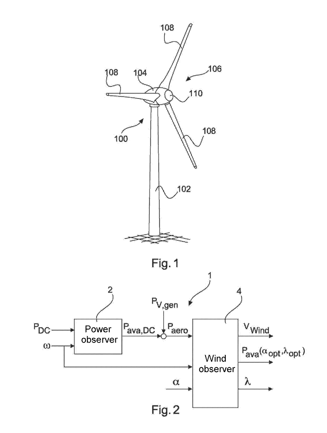
[0039]FIG. 1 shows a wind power installation 100 having a tower 102 and a nacelle 104. Arranged on the nacelle 104 there is a rotor 106 with three rotor blades 108 and a spinner 110. During operation, the rotor 106 is put into rotational movement by the wind and said rotor drives a generator in the nacelle 104 as a result thereof.

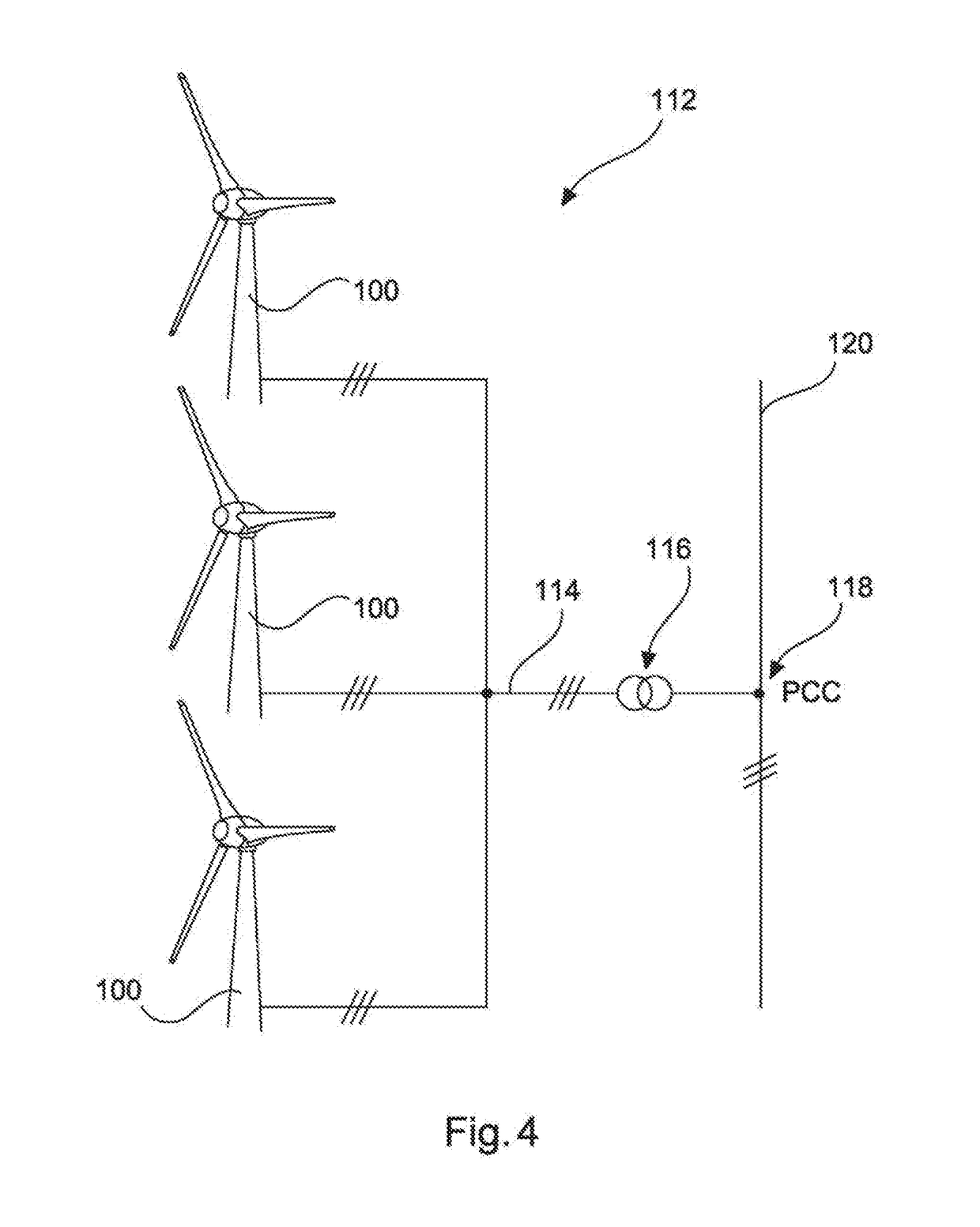
[0040]FIG. 4 shows a wind farm 112 with three wind power installations 100, which may be the same or different, in an exemplary manner. Consequently, the three wind power installations 100 are representative of, in principle, any number of wind power installations of a wind farm 112. The wind power installations 100 provide their power, specifically the produced current, in particular, by means of an electric farm grid 114. Here, the currents and powers of the individual wind power installations 100 produced in each case are added and provision is usually made of a transformer 116, which steps up the voltage in the farm, in order then to feed said voltage a...


PUM


Abstract

A method for determining an equivalent wind speed of a rotor blade plane of a wind power installation is provided. The wind power installation has a rotor with rotor blades that have adjustable blade angle. The said method includes determining an electric internal power available in the wind power installation depending on a captured electric power and a captured rotational speed of the rotor. The method includes and determining the equivalent wind speed depending on the determined available internal power and the captured rotational speed.

Description

TECHNICAL FIELD[0001]The present invention relates to a method for determining an equivalent wind speed of a rotor blade plane of a wind power installation. Moreover, the present invention relates to a wind power installation, configured to capture an equivalent wind speed of a rotor blade plane, and it relates to a wind farm.Description of the Related Art[0002]Wind power installations are known and have commonly one, usually a plurality of rotor blades, which rotate about a rotor axis and pass over a rotor area, i.e., a circular area, in the process. Since a wind power installation produces energy, and ultimately electric current, from the wind, the wind, and hence the wind speed thereof, is of great importance to the wind power installation.[0003]During normal, regular operation, a wind power installation can make do without capturing the wind speed, for example by virtue of setting a power, for example depending on a predetermined rotational speed / power characteristic, depending ...

Claims


Application Information

Patent Timeline
Patent Type & Authority Applications(United States)
IPC IPC(8): F03D7/02F03D17/00
CPCF03D7/0284F03D17/00F05B2260/821F05B2270/32F05B2270/327F05B2270/328F05B2270/335F05B2270/337Y02E10/72
Inventor ENGELKEN, SONKE
Owner WOBBEN PROPERTIES GMBH
Learn More