Check patentability & draft patents in minutes with Patsnap Eureka AI!

Piezoelectric two-phase flow ultrasonic atomization nozzle

Inactive Publication Date: 2019-02-21
JIANGSU UNIV
View PDF0 Cites 8 Cited by
  • Summary
  • Abstract
  • Description
  • Claims
  • Application Information

AI Technical Summary

Benefits of technology

The present invention provides a piezoelectric two-phase flow ultrasonic atomizing nozzle that can generate a large amount of atomization, ultra-small droplets size and directional spraying under low power consumption. Compared to conventional resonance modes, the present invention achieves this by changing the frequency of pressure fluctuation that affects the oscillation state of the two-phase fluid and resonance chamber. The fluctuating frequency of the two-phase fluid is greatly affected by the ambient temperature, and the eigenfiequency of the resonance chamber is basically constant, so it is easier for traditional fluid-dynamic ultrasonic atomizing nozzle to generate ultrasonic vibration in the resonance chamber. The present invention achieves this by changing the frequency of pressure fluctuation that affects the oscillation state of the two-phase fluid and resonance chamber, reducing the dependence on environmental temperature and other factors.

Problems solved by technology

However, the disadvantage is that the amount of atomization is small, and the droplets drift freely without direction.
Fluid-power ultrasonic atomization can produce large amount of atomization and can be sprayed to a specified area directly, and its disadvantage is that if the gas pressure is low, the droplet size is coarse and uneven.
So massive high pressure compressed air should be provided to get fine droplets, which is high energy consumption.
In view of the existing atomization technology, the present available atomization nozzle has the disadvantage that they can not generate large amount of atomization, ultra-small droplets size and directional spraying under low power consumption.
However, the nozzle can produce a large number of ultra-fine droplets and directional spraying under low power consumption.

Method used


Image

  • Piezoelectric two-phase flow ultrasonic atomization nozzle
  • Piezoelectric two-phase flow ultrasonic atomization nozzle
  • Piezoelectric two-phase flow ultrasonic atomization nozzle

Examples


Embodiment Construction

[0028]The present invention is further explained by the following combined with the drawings and the specific embodiments, but the protection scope of the invention is not limited to this.

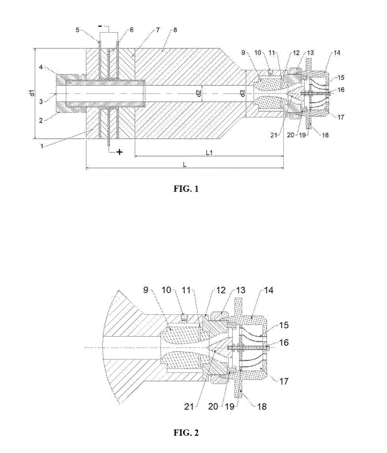
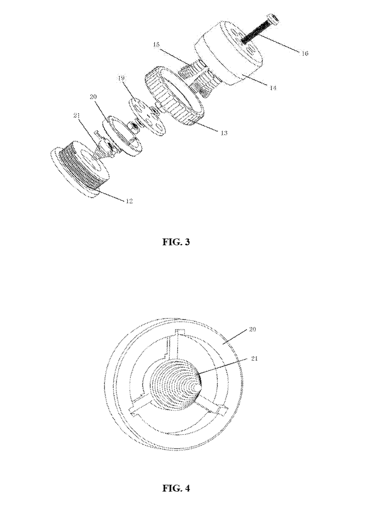
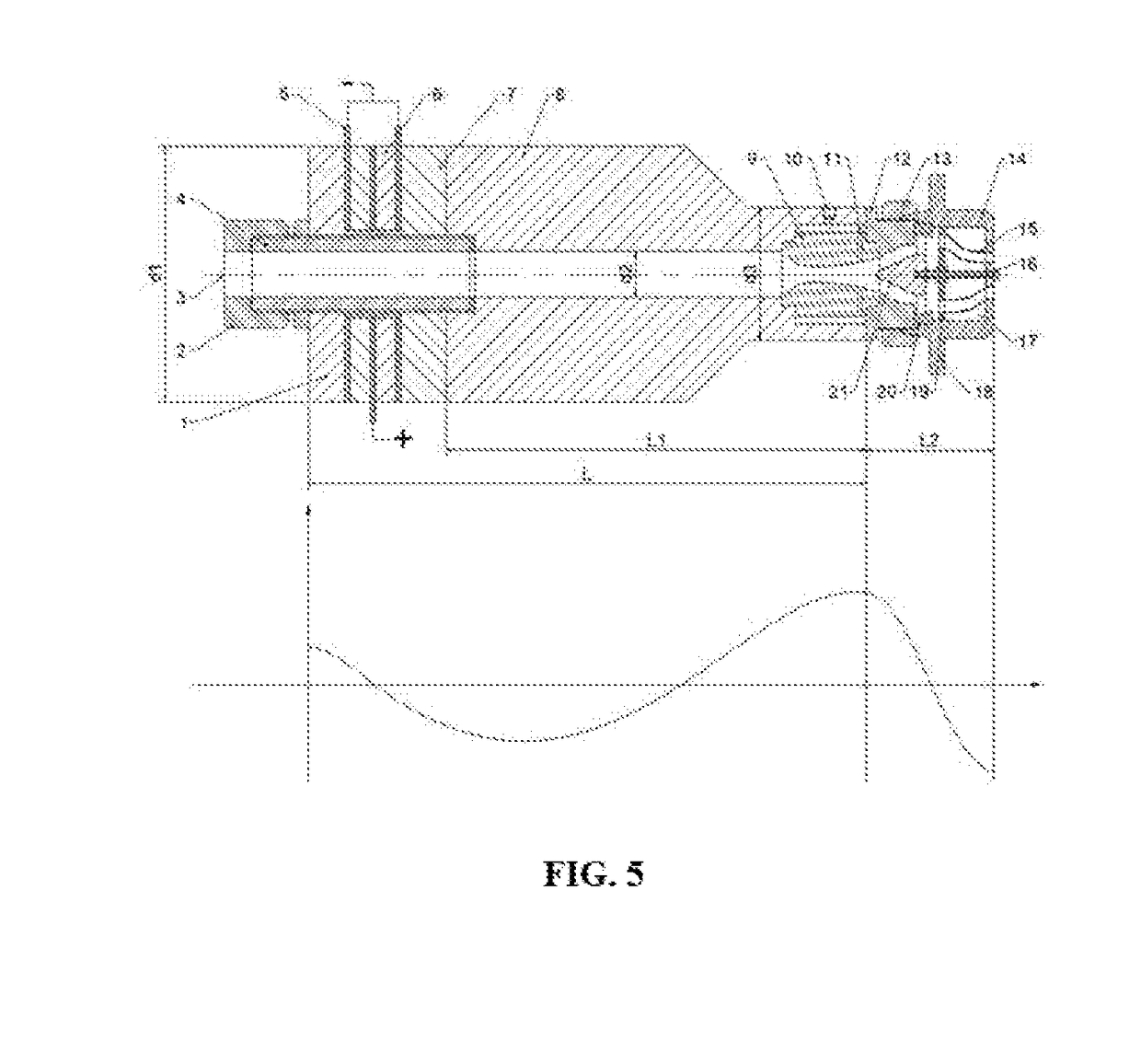
[0029]As shown in FIG. 1 and FIG. 2, a piezoelectric two-phase flow ultrasonic atomizing nozzle includes an air inlet joint (2), a connecting bolt (4), a piezoelectric vibrator (6), a horn (8), a Laval valve core (9), and a stepped cone valve (21), a second end cap (12) and a first end cap (14); the piezoelectric vibrator (6) and the horn (8) are fixedly connected by a connection bolt (4); the tail of the connecting bolt (4) is connected with the air inlet joint (2). The front end of the horn (8) is fixedly connected to the second end cap (12) with metal glue. The horn (8) is stepped shape with a conical transitional surface, and the material is aluminum 7075; the length L1 of the horn (8) is 66 mm, a wavelength of sonic wave at the horn (8). The diameter of the small end of horn (8) is 19 mm; a st...


PUM


Abstract

Disclosed is a piezoelectric two-phase flow ultrasonic atomization nozzle, comprising a piezoelectric vibrator (6), an amplitude transformer (8), a second end cap (12) and a first end cap (14). The piezoelectric vibrator (6) and the amplitude transformer (8) are connected via a connecting bolt (4). An air inlet connector (2) is installed at a tail portion of the connecting bolt (4). The second end cap (12) is fixed to the front end of the amplitude transformer (8). A Laval type valve core (9) is fixed in a stepped hole of the amplitude transformer (8) and a groove of the second end cap (12). A liquid inlet hole (10) is arranged in a wall face of the stepped hole of the amplitude transformer (8). A plurality of flow guide holes (11) is formed at the positions, close to an outlet, of the Laval type valve core (9) in the radial direction. The second end cap (12) is connected to the first end cap (14) in a threaded manner. A radial positioning ring (20) is arranged at a snapping groove of the back end of the first end cap (14). A step type taper valve (21) is installed on the radial positioning ring (20). The step type taper valve (21) and a vibration baffle (19) are connected via an adjusting bolt (16). A resonance chamber (17) is formed between the vibration baffle (19) and the top end of the first end cap (14). A plurality of hoses (15) is arranged in the resonance chamber (17). According to the piezoelectric two-phase flow ultrasonic atomization nozzle, a large number of superfine fog droplets can be generated in a low-energy-consumption operating condition, and the shortcoming that large atomization amount, small grain size, low energy consumption and directed spraying cannot be considered at the same time in the traditional technology is overcome.

Description

BACKGROUNDTechnical Field[0001]The present invention belongs to the field of ultrasonic atomization nozzle technology. In particular, it relates to a piezoelectric two-phase ultrasonic atomizing nozzle.Related Art[0002]At present, in the ultrasonic atomization technology field, there are mainly two methods for generating ultrasonic vibrations: one is to use electro-acoustic transducers to generate ultrasonic waves, and the other is to use fluids power to generate ultrasonic waves. The two methods have their own advantages and disadvantages. The droplet generated by atomizing nozzles of the electroacoustic transducer is uniform and the energy consumption is small. The particle size of the droplets changes with the design frequency of the piezoelectric vibrator (6), and the higher the frequency, the smaller the droplet size. However, the disadvantage is that the amount of atomization is small, and the droplets drift freely without direction. Fluid-power ultrasonic atomization can prod...

Claims


Application Information

Patent Timeline
IPC IPC(8): B05B17/06B05B7/12
CPCB05B17/0607B05B7/12B05B17/0623B05B17/0615B05B7/0483B05B17/063B05B17/0669
Inventor GAO, JIANMINMA, JUNLONG
Owner JIANGSU UNIV
Features
  • R&D
  • Intellectual Property
  • Life Sciences
  • Materials
  • Tech Scout
  • Unparalleled Data Quality
  • Higher Quality Content
  • 60% Fewer Hallucinations
Learn More