
Systems and methods for axial impact resistance in electric motors

a technology of axial impact resistance and electric motor, which is applied in the functional characteristics of elastic dampers, springs/dampers, mechanical devices, etc., can solve the problems of premature failure or unintended noise of operation, damage to bearings, and compression of bearings

Active Publication Date: 2019-02-21
IFIT INC
View PDF0 Cites 39 Cited by
  • Summary
  • Abstract
  • Description
  • Claims
  • Application Information

AI Technical Summary

Benefits of technology

This patent describes a system for providing torque, which includes a stator, rotor, axle, endcap, endbell, and compliant member. The system generates torque by rotating the rotor relative to the stator using the axle, which is supported by the stator and rotor. The compliant member is positioned between the rotor and endcap or between the rotor and endbell and is made of a resilient material that can expand and contract to absorb and store energy during operation. The technical effect of this system is to provide a more efficient and effective mechanism for generating torque, which can be useful in various applications such as electric vehicle systems.

Problems solved by technology

Force applied to the bearings in the longitudinal direction can compress the bearings perpendicular to the intended operation direction and damage the bearings.
Because the bearings inside the motor are constructed to have very tight tolerances to reduce vibration, even small deformation to the bearings or race due to the impact from a drop may introduce vibrations into the bearings and cause premature failure or unintended noise during operation.

Method used


Image

  • Systems and methods for axial impact resistance in electric motors
  • Systems and methods for axial impact resistance in electric motors
  • Systems and methods for axial impact resistance in electric motors

Examples


Embodiment Construction

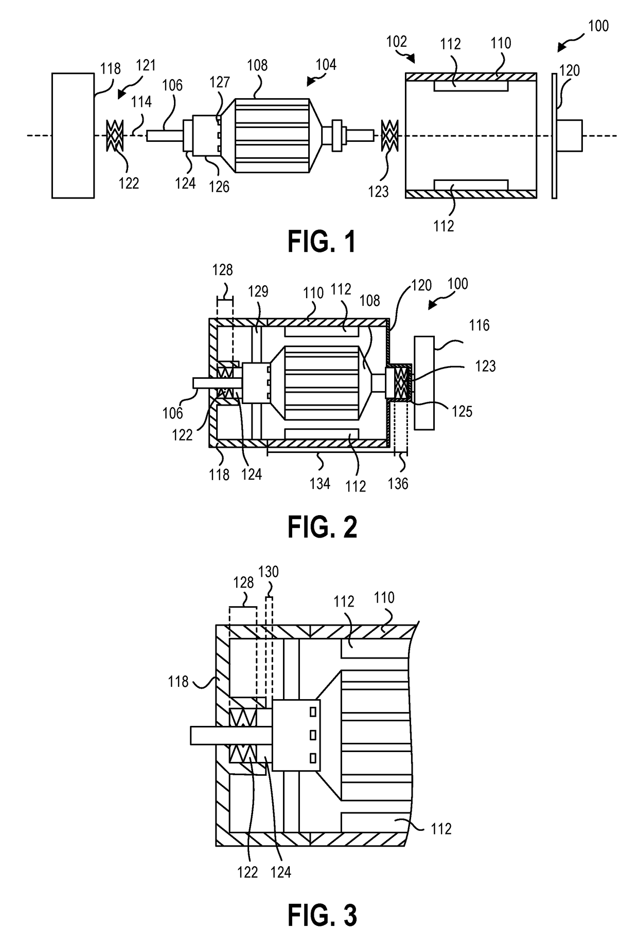
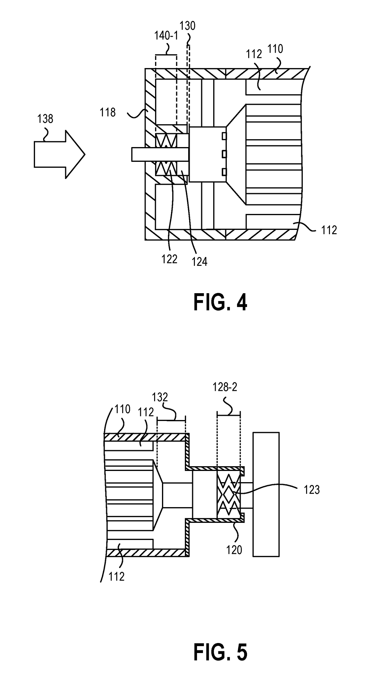
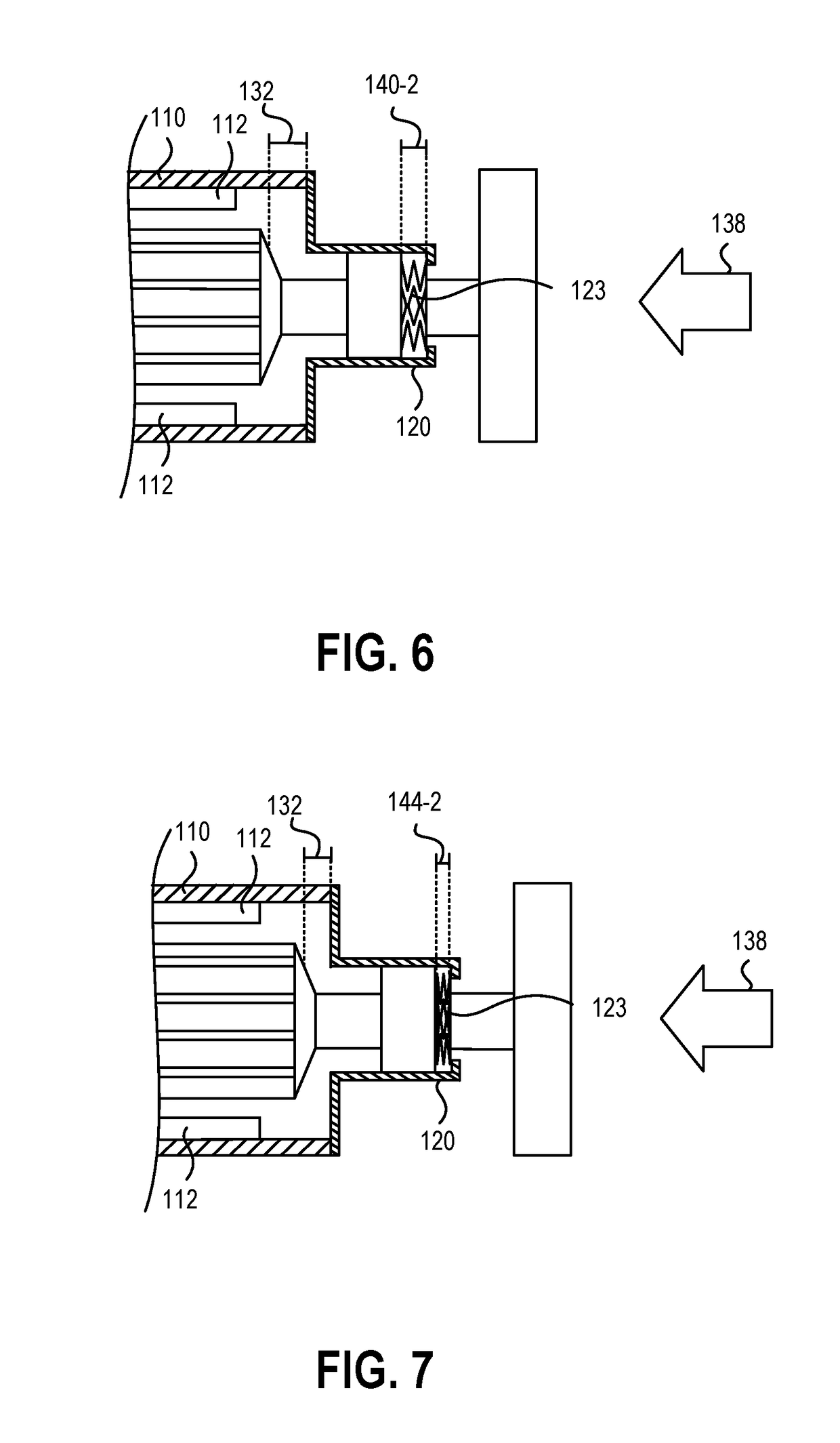
[0024]FIG. 1 is a perspective exploded view of an embodiment of an electric motor 100, according to the present disclosure. The electric motor 100 includes a stator 102 and a rotor 104. The rotor 104 is rotatable about an axle 106 that extends along the rotor 104. The rotor 104 includes an armature 108 that rotates with or around the axle 106 to rotate relative to the stator 102. The stator 102 includes a permanent magnet 112 that interacts with the electromagnets of the armature 108 to rotate the armature 108 and axle 106 of the rotor 104 about a longitudinal axis 114.

[0025]The axle 106 is coupled to a flywheel 116 of the electric motor 100. The rotation of the rotor 104 about the longitudinal axis 114 rotates the flywheel 116. The rotating flywheel 116 functions to increase the moment of inertia of the rotor 104. Increasing the moment of inertia of the rotor 104 provides a smoother and more consistent angular speed for the rotor 104 during operation.

[0026]During shipping, storage,...


PUM


Abstract

A system for providing torque includes a stator, a rotor, an axle, an endcap, an endbell, and a compliant member. The stator has a first end and a second end opposite the first end with a chamber therein. The rotor is at least partially positioned in the chamber and rotatable relative to the stator about a longitudinal axis. The axle has a first end, a second end opposite the first end, and supports the rotor. The endcap is located at a first end of the stator and adjacent to the first end of the axle, and the endbell is located at the second end of the stator and adjacent to the second end of the axle. The compliant member is positioned relative to the axle between a portion of the rotor and one of the endbell and the endcap.

Description

CROSS-REFERENCE TO RELATED APPLICATIONS[0001]This application claims priority to provisional patent application No. 62 / 546,547 entitled “SYSTEMS AND METHODS FOR AXIAL IMPACT RESISTANCE IN ELECTRIC MOTORS” filed Aug. 16, 2017 and provisional patent application No. 62 / 552,591 entitled “SYSTEMS AND METHODS FOR AXIAL IMPACT RESISTANCE IN ELECTRIC MOTORS” filed Sep. 1, 2017, which applications are herein incorporated by reference for all that they disclose.BACKGROUNDTechnical Field[0002]This disclosure generally relates to electric motors. More particularly, this disclosure generally relates to one or more features on or in contact with the rotor of an electric motor to protect the electric motor from damage due to axial impacts.Background and Relevant Art[0003]Electric motors operate by rotating a rotor relative to a stator to generate torque. The rotor conventionally rotates relative to the stator and around a longitudinal axis on a bearing or set of bearings. Force applied to the bear...

Claims


Application Information

Patent Timeline
IPC IPC(8): H02K5/16F16F1/32F16F1/44H02K11/20
CPCH02K5/16F16F1/328F16F1/445H02K11/20F16F2236/04F16F2238/02H02K2205/00H02K2205/03F16F15/04F16F15/315H02K5/24H02K2213/06F16F2228/007F16F7/12H02K5/161
Inventor TINNEY, EVAN CHARLES
Owner IFIT INC
Learn More