Method and device for wireless communication between connected objects and gateways

a wireless communication and connected object technology, applied in the field of communication protocols, can solve the problems of limited number of timeslots that can be assigned by a gateway to connected objects, the type of protocol presents a number of limitations, and the management of usage time is far from optimal, so as to achieve good transmission of signals, improve the use of useful time, and improve the effect of transfer ra

Active Publication Date: 2019-02-21
CROHAS HENRI
View PDF5 Cites 17 Cited by
  • Summary
  • Abstract
  • Description
  • Claims
  • Application Information

AI Technical Summary

Benefits of technology

[0040]Preferably, the gateway which wants to receive a message scans different transfer rates simultaneously or sequentially and listens on the channel or channels assigned in the beacon message to detect a message. This step allows better use of the useful time by minimizing the transfer times when the connected objects are close to the gateway and they use a high transfer rate. Also, that makes it possible to guarantee a good transmission of the signals at long range and at low power when the connected object is further

Problems solved by technology

This type of protocol presents a number of limitations.
Firstly, the management of the usage time is far from being optimal because the subdivision of the periodic signal into time windows and time subwindows extends the delays between the communications.
Secondly, if the number of gateways is increased, the duration of the periodic signal increases (or the number of subwindows decreases) which commensurately extends the delays between the communications (or reduces the number of subwindows that can be assigned by a gateway).
Thirdly, the number of timeslots that can be assigned by a gateway to connected objects is limited for the periodic signal not to become too long.
The risks of saturation of the network therefore become significant.
Fourthly, the frequency usage of the network is limited and not optimized.
Fifthly, the connected objects have to be resynchronized regularly to be able to communicate in its time slot, which consumes energy.
In conclusion, this protocol lacks flexibility, is ill suited to objects communicating occasionally and does not optimize the use of the time that can be used for communications.
This protocol also presents a number of defects.
Conse

Method used


Image

  • Method and device for wireless communication between connected objects and gateways
  • Method and device for wireless communication between connected objects and gateways
  • Method and device for wireless communication between connected objects and gateways

Examples


Embodiment Construction

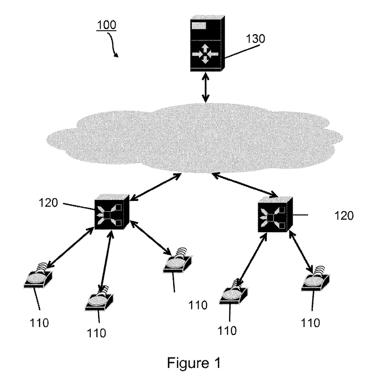
[0065]FIG. 1 shows an example of wireless communication network 100 comprising a plurality of wireless connected objects 110, at least one gateway 120. Preferably, the network comprises a plurality of gateways. Preferably, the gateway or gateways are connected to a central server 130. This connection can be a local area network connection, a wired (Ethernet) or wireless (Wi-Fi) internet connection. Preferably, the server is a cloud-type server. Preferably, the connected objects—gateways network is a low-power wide area wireless network, LP-WAN.

[0066]The standard term “connected object” should be understood to be an object which is actually connected to a network or which is connectable to a network.

[0067]In the present invention, the connected objects are not linked to a particular gateway, in other words, they are not registered in a fixed manner with a gateway. They can change gateway as a function, for example, of the quality of the beacon signal received, of the presence of a ne...


PUM


Abstract

Methods of communication in a wireless communication network having a plurality of connected objects, a gateway and a central server. These elements communicate with one another via messages sent and received on frequency channels. A channel is reserved for the periodic transmission of tag messages by the gateways, thereby allowing the organization and optimization of the network usage and communication time.

Description

TECHNICAL FIELD[0001]The invention relates to the communication protocols in a radiofrequency network and, more particularly, to methods allowing this type of communication within a wireless network with long range and low power. In its application in a layered model, the invention relates to the protocol of the link layer (the layer comprising the Media Access Control MAC). The invention relates also to devices implementing these methods.STATE OF THE ART[0002]Methods for exchanging data in a wireless network comprising connected objects, gateways and a central server are known. For example, the patent application US 2014 / 0111313 discloses a communication method in which a connected object must perform numerous steps before connecting to a gateway. These steps consist in:[0003]listening for a periodic signal containing a beacon signal transmitted by at least one gateway;[0004]synchronization of the internal clock of the connected object with the beacon signal;[0005]identification of...

Claims


Application Information

Patent Timeline
IPC IPC(8): H04W74/08H04B17/318H04W40/24
CPCH04W74/0866H04B17/318H04W40/244H04W88/16H04W48/20H04W84/10H04W84/18
Inventor CROHAS, HENRI
Owner CROHAS HENRI
Why Eureka
Try Eureka