Scanning probe microscope

a scanning probe and microscope technology, applied in the field of scanning probe microscopes, can solve the problems of unsuitable sample scanning, unsatisfactory scanning effect, and inability to achieve the effect of reducing interdependence and maximising the benefits of design

Inactive Publication Date: 2019-02-28
OXFORD INSTR ASYLUM RES INC
View PDF4 Cites 1 Cited by
  • Summary
  • Abstract
  • Description
  • Claims
  • Application Information

AI Technical Summary

Benefits of technology

[0007]According to the present invention, a beam system is used to manipulate the location of measurement of a probe by a detector for the purpose of following the probe as it is scanned in a scanning probe configuration. Furthermore, the optical system in the form of the beam system for this invention is designed such that the entirety of the AFM probe deflection detection system or its parts, including any final lenses or objective for focusing the beam onto the probe, are not required to be attached to or carried by the scanner or probe. This greatly reduces the interdependence between the measurement system and the scanner system and allows them to be modular.
[0008]The light beam is typically directed at the probe by one of more optical elements and none of the optical elements which direct the light beam so as to be incident upon the probe are mounted to the scanner or the probe. Thus each of the said optical elements is physically mounted to the beam system rather than the probe or scanner. The light beam typically only interacts with the probe by simple reflection from a part of the probe which is or acts as a mirror. The scanner to which the probe is mounted may therefore be configured mechanically to move entirely independently of the beam system. As such the beam system is decoupled physically and completely from the probe or scanner which maximises the benefits from the design, particularly in terms of performance benefits resulting from weight reduction.
[0014]In another embodiment which is a “single pass” arrangement the beam system comprises a light source, a first beam separator, a lens system, a beam steering device, a second beam separator, an objective and a focusing lens system and wherein the light source emits the light beam which is directed in a first direction by the first beam separator, through the lens system to the beam steering device, wherein the beam steering device controls the direction of the light beam and directs the light beam back, in a second direction, opposite to the first direction, through the lens system, through the first beam separator and through the second beam separator to the objective, wherein the light passes through the objective in the second direction and is incident upon the probe, wherein the light beam is reflected from the probe back through the objective in the first direction and passes through the second beam separator, to the first beam separator and then through the focusing lens system to the detector. However in this embodiment the movement of the probe is not automatically removed by the optics and instead this effect is achievable using the additional focusing lens system. In such cases the beam system is advantageously configured to project the back focal plane of the objective on to the detector.
[0021]The position sensitive detector used by the tracking system may be mounted to the probe or the scanner. Whilst this may simplify the number of system components it may add unwanted weight to the probe or scanner. In an alternative arrangement the position sensitive detector is remote from the scanner and probe and the tracking light beam follows a path through the beam system which is generally parallel to that of the light beam used for monitoring the deflection of the probe. Thus the optics of the beam system may be used to conveniently provide the tracking light beam to and from the probe in addition to the light beam used for monitoring the probe deflection. The tracking system may comprise a tracking light source, a tracking beam separator and a tracking lens system and wherein the tracking light source emits the tracking light beam which is incident upon the tracking beam separator and then the tracking lens, and then enters the beam system via the first beam separator, travels to and from the probe using the beam system, is received from the first beam separator, passes through the tracking lens system and tracking beam separator and is received at the position sensitive detector. A reflective target, such as a retro-reflector, may be mounted on or near the scanned probe to reflect the tracking light beam.

Problems solved by technology

However, as many applications require large samples to be measured or that multiple locations or multiple samples are to be measured that are much further apart than the scan size, it becomes impractical to scan the sample while maintaining or improving performance requirements such as scan speed, noise and stability.
However, the scan size in this early adoption was severely restricted so as to maintain the beam deflection laser spot on the back of the probe.
However, the optical detecting module, which includes the laser source, position sensitive detector, the alignment mechanisms and the supporting structure can result in an undesirable amount of mass and complexity attached to the scanner, particularly on the Z axis mechanism.
This puts severe limits on the speed and stability of the overall design.
In the case of Gotthard et al, the implementation teaches little for how this would be used for X and Y direction tracking use and in practice still resulted in large deflection errors in the Z direction.

Method used


Image

  • Scanning probe microscope
  • Scanning probe microscope
  • Scanning probe microscope

Examples


first embodiment

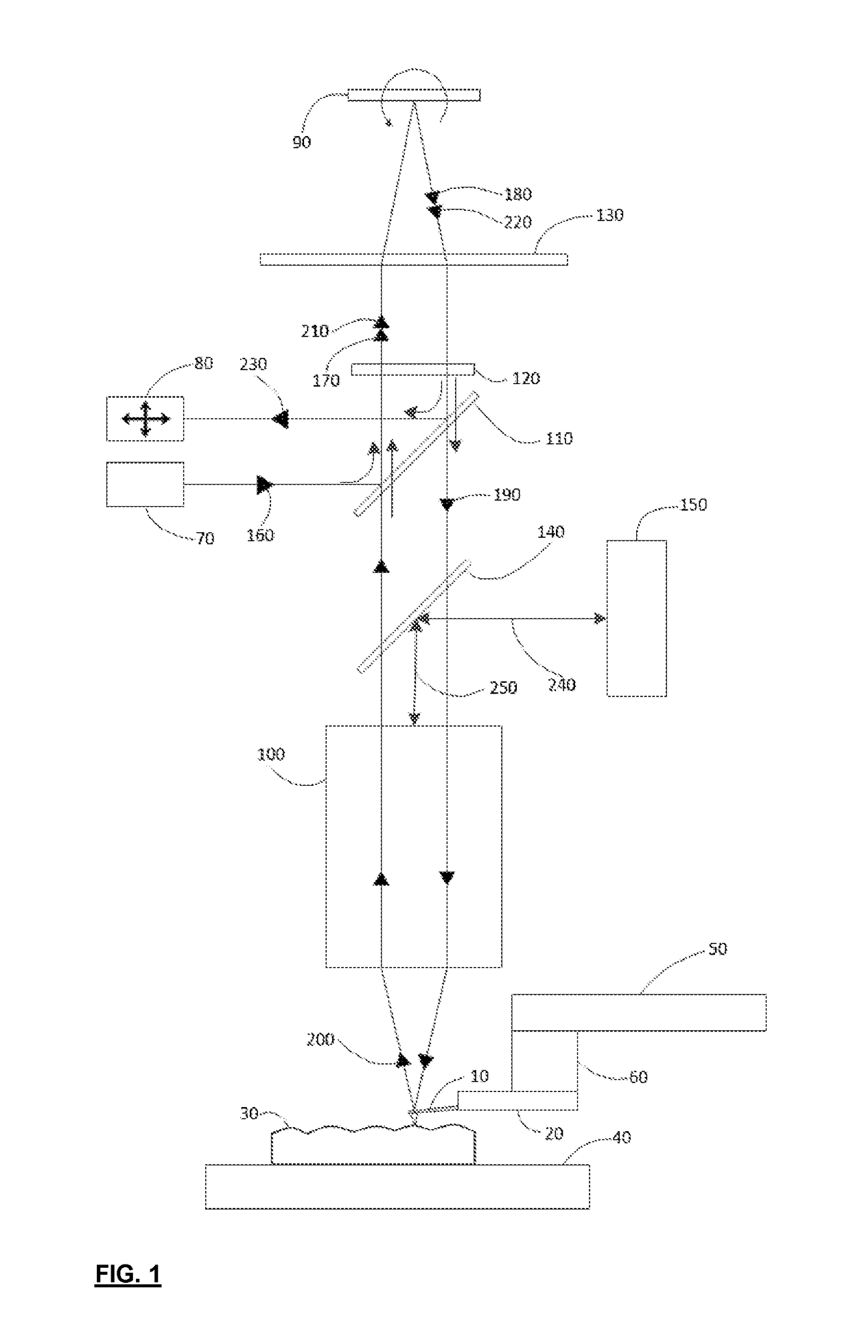
[0039]FIG. 1 shows an overall diagram of the present invention. The Probe 10 is attached to and carried by a Probe Holder 20. To perform measurements and move Probe 10 relative to the Sample 30, the Probe 10 and Probe Holder 20 are scanned relative to the Sample 30 in one or more orthogonal directions, namely in the X and Y directions that are parallel to the plane of the Sample 30 surface by the XY Scanner 50 and in the Z direction that is normal to the Sample 30 surface by the Z Scanner 60. The XY Scanner 50 moves the probe in the X and Y directions and the Z Scanner 60 moves the probe in the Z direction. The Sample 30 is supported by a Sample Support Structure 40, a form of sample holder, which may consist of a means to move the sample over larger distances than otherwise provided by the XY Scanner 50 and the Z Scanner 60 for the purposes of performing measurements at different locations on the Sample 30. Neither item 70 thru 150 discussed below are carried by the XY Scanner 50 o...

second embodiment

[0051]FIG. 5 shows a second embodiment where the Beam Steering Device 90 is reflected upon only one time as the beams travel from the Light Source 70 to the PSD 80. This configuration is referred to as a “single-pass” configuration. In this “single-pass” configuration, the PSD 80 is located on the opposite side of the Beam Splitter 110 from the Light Source 70. As in FIG. 1 and FIG. 2, the path taken from the Light Source 70 to the Probe 10 is generally the same, however upon reflection from the Probe 10 beam 200 is again collected by the Objective 100. It passes through the Top View Beam Splitter 140 however then reflects from the Beam Splitter 110 to follow path 410 towards the PSD 80. Because the reflected beam 200 is not “de-scanned” by returning through the Beam Steering Device 90 a second time, it is advantageous to add Focus Lens 400 that projects the Back Focal Plane (BFP) of the Objective 100 onto the PSD 80. The PSD 80 is optically located to remain sensitive to the positi...

third embodiment

[0052]FIG. 6 is a diagram showing a third embodiment where there are two separate telescope lens systems 130 and 500. This configuration is absent the Beam Splitter 110 of the previous embodiments and does not require polarization dependent components, as described in the previous embodiments. However this configuration has other added complications such as off-axis angle coupling particularly as the Beam Steering Device 90 scans in the out-of-plane Y direction. This can occur due to the overall larger average reflecting angle at the Beam Steering Device 90 as compared to the almost normal angles realized in the preferred embodiment shown in FIG. 1 and FIG. 2. The beams reflect from the Beam Steering Device 90 two times, as in the preferred embodiment, however the overall angle of the Beam Steering Device 90 is closer to 45 degrees to the system, therefore this embodiment is referred to as the “45-degree dual-pass” configuration. The Light Source 70 generates a beam 160. A Lens Syst...


PUM


Abstract

A scanning probe microscope has a probe configured to move across the surface of a sample to be monitored. A scanner, to which the probe is mounted, moves the probe across the sample surface such that the probe is deflected in accordance with the structure of the sample surface. A beam system directs a light beam at the probe during the movement of the probe across the sample surface and a detector monitors the deflection of the probe using the light beam. The arrangement is such that the scanner is physically independent of the beam system.

Description

FIELD OF THE INVENTION[0001]The present invention relates directly to the field of scanning probe microscopes (SPMs) and more particularly relates to a tip scanning SPM in conjunction with a deflection beam probe sensing technique.BACKGROUND OF THE INVENTION[0002]Scanning probe microscopes (SPMs) can be used for a wide range of applications to measure materials with molecular or even atomic level resolution. The range of applications can often drive the need for the instrument to accommodate a wide range of sample and experimental conditions such as; large sample size, multiple sample or multiple site measurements on a sample, or maintaining the sample in a variety of environments or conditions.[0003]The term SPM refers to a more general group of instruments where the three most common types are; Atomic Force Microscopes (AFM), Scanning Tunnelling Microscopes (STM), and Near-Field Scanning Optical Microscopes (NSOM). Traditional SPMs, particularly atomic force microscopes (AFMs), ar...

Claims


Application Information

Patent Timeline
Patent Type & Authority Applications(United States)
IPC IPC(8): G01Q70/06G01Q70/08G01Q10/04G01Q20/04
CPCG01Q70/06G01Q70/08G01Q90/00G01Q20/04G01Q10/04G01Q10/065G01Q20/02
Inventor GRIGG, DAVID A.WALTERS, DERONZHANG, HAIGANGCLEVELAND, JASON
Owner OXFORD INSTR ASYLUM RES INC
Why Eureka
Try Eureka