Light source apparatus and projector

a light source and projector technology, applied in the direction of projectors, polarising elements, instruments, etc., can solve the problems of undesirable increase in the size of the entire light source apparatus, and achieve the effects of improving reliability, reducing size, and improving reliability

Active Publication Date: 2019-02-28
SEIKO EPSON CORP
View PDF0 Cites 7 Cited by
  • Summary
  • Abstract
  • Description
  • Claims
  • Application Information

AI Technical Summary

Benefits of technology

[0021]The projector according to the aspect described above, which includes the light source apparatus includ

Problems solved by technology

However, since the light beam flux emitted from the first light emitter and the light beam flux emitted from the second light emitter

Method used


Image

  • Light source apparatus and projector
  • Light source apparatus and projector
  • Light source apparatus and projector

Examples


Embodiment Construction

[0029]An embodiment of the invention will be described below in detail with reference to the drawings.

[0030]In the drawings used in the following description, a characteristic portion is enlarged for convenience in some cases for clarity of the characteristic thereof, and the dimension ratio and other factors of each component are therefore not always equal to actual values.

[0031]An example of a projector according to the present embodiment will be described.

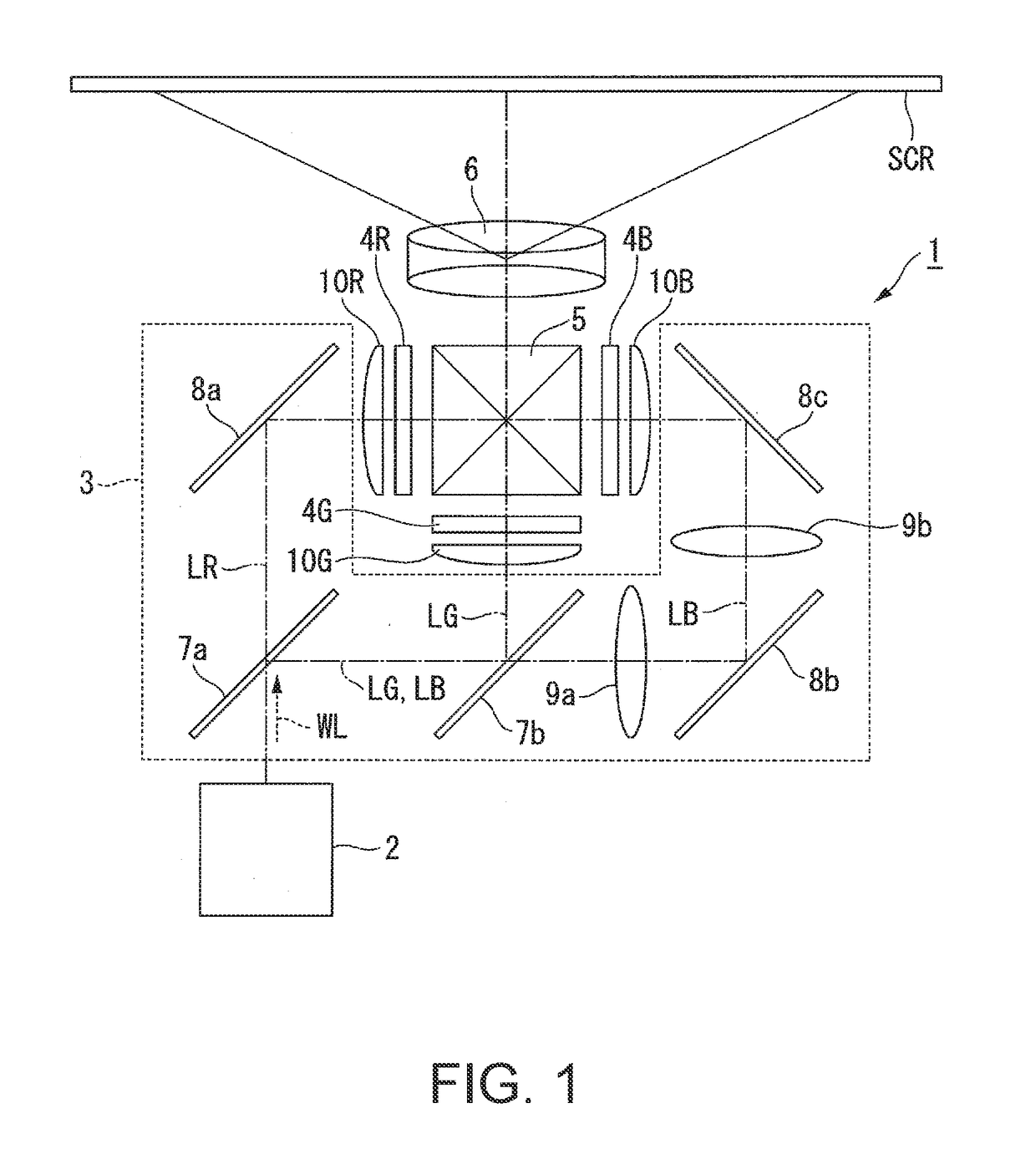
[0032]FIG. 1 shows a schematic configuration of the projector according to the present embodiment.

[0033]A projector 1 according to the present embodiment is a projection-type image display apparatus that displays color video images on a screen SCR, as shown in FIG. 1. The projector 1 includes a light source apparatus 2, a color separation system 3, a light modulator 4R, a light modulator 4G, a light modulator 4B, a light combining system 5, and a projection optical apparatus 6.

[0034]The color separation system 3 separates white ...


PUM


Abstract

A light source apparatus includes a light source section that outputs first and second light beam fluxes, first and second polarization separation elements, a rotary diffuser plate that diffuses the first light beam flux and the second light beam flux, a first retardation film that converts the incident second light beam flux polarized in a first direction into the second light beam flux polarized in a second direction, and a wavelength conversion element on which the first light beam flux polarized in the first direction and the second light beam flux polarized in the second direction, are incident and which converts the first and second light beam fluxes into a third light beam flux that belongs to a wavelength band different from the wavelength band to which the first and second light beam fluxes belong. The third light beam flux passes through the first and second polarization separation elements.

Description

BACKGROUND1. Technical Field[0001]The present invention relates to a light source apparatus and a projector.2. Related Art[0002]In recent years, a projector uses a laser light source, which produces high-luminance, high-output light. For example, JP-A-2017-062294 discloses a projector using not only fluorescence produced by incidence of blue laser light on a phosphor layer but diffused blue laser light.[0003]In the invention disclosed in JP-A-2017-062294, light outputted from a first light emitter is divided into two light beam fluxes, which are caused to be incident on a diffuser plate and the phosphor layer, and light outputted from a second light emitter is divided into two light beam fluxes, which are caused to be incident on the diffuser plate and the phosphor layer. The optical density of the light incident on the phosphor layer and the diffuser plate is thus reduced.[0004]The configuration described above reduces the burden on the diffuser plate in terms of the optical densit...

Claims


Application Information

Patent Timeline
IPC IPC(8): G03B21/28G02B5/30G03B21/20G02B5/02G02B27/10
CPCG03B21/28G02B5/3083G03B21/2033G02B5/0205G02B27/1006G02B27/283G02B27/286G03B21/2073G03B21/204G03B21/2066G02B27/141G02B27/149
Inventor AKIYAMA, KOICHI
Owner SEIKO EPSON CORP
Why Eureka
Try Eureka