Time-To-Digital Converter, Circuit Device, Physical Quantity Measurement Apparatus, Electronic Instrument, And Vehicle

Active Publication Date: 2019-02-28
SEIKO EPSON CORP
View PDF2 Cites 14 Cited by
  • Summary
  • Abstract
  • Description
  • Claims
  • Application Information

AI Technical Summary

Benefits of technology

[0006]An advantage of some aspects of the invention is to solve at least a part of the problem

Problems solved by technology

Therefore, the characteristics of the clock signal from each of the oscillators (for example, temperature characteristic, process variation, and jitter characteristic) affect the time clocking accuracy, undesirably resulting in ins

Method used


Image

  • Time-To-Digital Converter, Circuit Device, Physical Quantity Measurement Apparatus, Electronic Instrument, And Vehicle
  • Time-To-Digital Converter, Circuit Device, Physical Quantity Measurement Apparatus, Electronic Instrument, And Vehicle
  • Time-To-Digital Converter, Circuit Device, Physical Quantity Measurement Apparatus, Electronic Instrument, And Vehicle

Examples


Embodiment Construction

[0052]A preferable embodiment of the invention will be described below in detail. It is not intended that the present embodiment described below unduly limits the contents of the invention set forth in the appended claims, and all configurations described in the present embodiment are not necessarily essential as solutions provided by the invention.

1. Time-to-Digital Converter

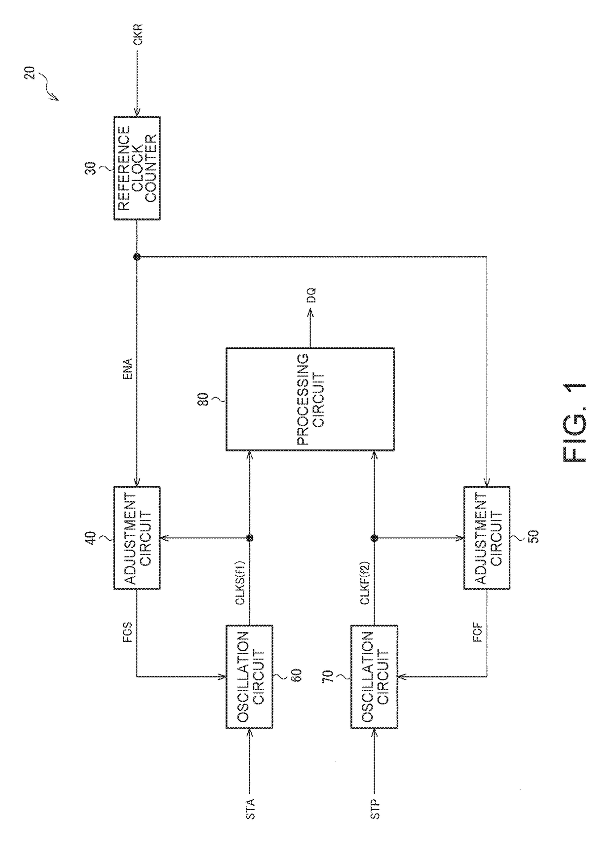
[0053]FIG. 1 shows an example of the configuration of a time-to-digital converter according to the present embodiment. A time-to-digital converter 20 can include an oscillation circuit 60 (first oscillation circuit), an oscillation circuit 70 (second oscillation circuit), an adjustment circuit 40 (first adjustment circuit), an adjustment circuit 50 (second adjustment circuit), and a processing circuit 80. The time-to-digital converter 20 can further include a reference clock counter 30 (counter). The time-to-digital converter to which the embodiment of the invention is applied does not necessarily have the conf...


PUM


Abstract

A time-to-digital converter includes a first oscillation circuit that starts oscillating at the transition timing of a first signal and generates a first clock signal having a first clock frequency, a second oscillation circuit that starts oscillating at the transition timing of a second signal and generates a second clock signal having a second clock frequency, a first adjustment circuit that adjusts the oscillation frequency of the first oscillation circuit based on a reference clock signal, a second adjustment circuit that adjusts the oscillation frequency of the second oscillation circuit based on the reference clock signal, and a processing circuit that converts the time difference between the transition timing of the first signal and the transition timing of the second signal into a digital value based on the first and second clock signals.

Description

BACKGROUND1. Technical Field[0001]The present invention relates to a time-to-digital converter, a circuit device, a physical quantity measurement apparatus, an electronic instrument, a vehicle, and the like.2. Related Art[0002]There has been a known time-to-digital converter that converts time into a digital value. As an example of a time-to-digital converter of related art that measures a time difference between a first signal and a second signal produced at arbitrary timings, there is, for example, a related-art technology disclosed in JP-A-64-079687.[0003]JP-A-64-079687 describes a time clocking circuit that includes a first oscillator that starts oscillating at a frequency f when a start signal is produced and a second oscillator that starts oscillating at a frequency f+Δf in when a stop signal is produced and compares the phase of a clock signal from the first oscillator with the phase of a clock signal from the second oscillator to measure the time gap between the start signal...

Claims


Application Information

Patent Timeline
IPC IPC(8): G04F10/00B60R16/023H03L7/099H03L7/07
CPCG04F10/005B60R16/0232H03L7/0996H03L7/0992H03L7/07H03L7/0805H03L7/093H03L7/23H03L2207/06
Inventor SUDO, YASUHIRO
Owner SEIKO EPSON CORP
Why Eureka
Try Eureka