Heterogeneous energy storage system and method of controlling a heterogeneous energy storage system

Pending Publication Date: 2019-02-28
UNIV OF COLORADO THE REGENTS OF +1
View PDF2 Cites 4 Cited by
  • Summary
  • Abstract
  • Description
  • Claims
  • Application Information

AI Technical Summary

Benefits of technology

The patent text describes a system that allows for the use of different types of energy cells that work together without needing to convert or manage power. This results in a more efficient and cost-effective system.

Problems solved by technology

Even though heterogeneous energy storage systems offer considerable reduction in weight, in most cases, single chemistry solutions are used in industry due to multiple factors: (1) cells of different types operate with different voltages and current limits and are difficult to combine in series or parallel, (2) solutions presented in the literature to date either combine modules directly in parallel, requiring cell characteristics to match, utilize only one module type at a time, resulting in an underutilized system, or require power converters to operate as series buffers between heterogeneous modules, resulting in high cost, low efficiency, and increased size and weight, and (3) the control systems considered apply brute-force extensions of standard passive battery management systems (BMS) to all modules, resulting in increased cost.

Method used


Image

  • Heterogeneous energy storage system and method of controlling a heterogeneous energy storage system
  • Heterogeneous energy storage system and method of controlling a heterogeneous energy storage system
  • Heterogeneous energy storage system and method of controlling a heterogeneous energy storage system

Examples


Embodiment Construction

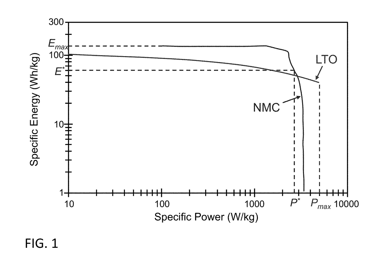
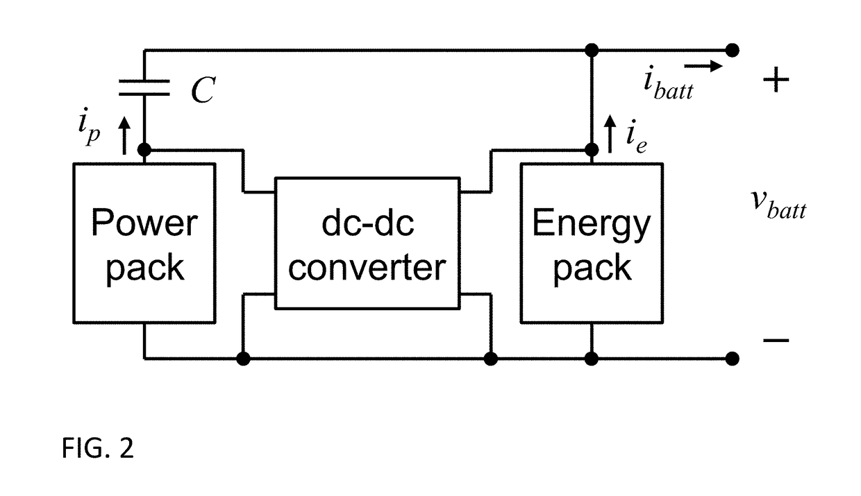
[0016]In various implementations, an energy storage system architecture and method of controlling such a system is provided. For example, systems and methods that realize full capabilities of heterogeneous energy and power optimized cells without the loss, complexity and cost associated with power conversion or power management functions may be provided. In one implementation, for example, an architecture named Composite Heterogeneous Energy Storage System (CHESS) uses capacitors in addition to different types of battery cells (see FIG. 2 as an example implementation) and may be used to achieve breakthrough performance. For example, the CHESS system of FIG. 2 offers more than 50% longer EV range for equal weight, volume, life and cost compared to commercial state-of-the-art EV battery systems.

[0017]In one particular implementation, for example, a power pack (comprising power optimized cells) is ac coupled to an energy pack (comprising energy optimized cells) using a capacitive devic...


PUM


Abstract

A heterogeneous energy storage device and a method for controlling a heterogeneous energy storage device are provided. In one implementation, a heterogeneous energy storage device is provided. The heterogeneous energy storage device includes a first energy storage device, a second energy storage device and a capacitive device. The first energy storage device has a first energy capacity and a first power to energy ratio (P / E). The second energy storage device has a second total energy capacity and a second P / E ratio different from the first P / E ratio. The capacitive device is coupled in series with the first energy storage device, wherein the second energy storage device is coupled in parallel with the series combination of the capacitive device and the first energy storage device. In another implementation, a method of controlling a heterogeneous energy storage device including a first energy storage device and a second energy storage device is provided. In this implementation, the method includes: providing a capacitive device in series with the first energy storage; coupling the second energy storage device in parallel with the series combination of capacitive device and the first energy storage device, wherein the capacitive device provides DC decoupling between the first energy storage device and the second energy storage device.

Description

CROSS-REFERENCE TO RELATED APPLICATIONS[0001]This application is a 371 of PCT application no. PCT / US2017 / 019306 filed on Feb. 24, 2017, which claims the benefit of U.S. provisional application No. 62 / 299,212, filed Feb. 24, 2016, both of which are hereby incorporated by reference as though fully set forth herein.BACKGROUNDField[0002]The instant invention relates to heterogeneous energy storage systems.Background[0003]Battery systems for electric vehicles (EV) and other applications can be improved in theory by combining power optimized cells and energy optimized cells rather than compromising with a single chemistry that must meet both the power and energy demands of the application. A conventional energy storage system (ESS) is optimized by selecting single-chemistry cells with specific power to energy ratio P* / E* equal to the application required power to energy (P / E) ratio, as shown in FIG. 1 for an example Li-ion NMC chemistry. FIG. 1 also shows a Ragone chart for the Li-ion LTO...

Claims


Application Information

Patent Timeline
IPC IPC(8): H01M10/42B60L11/18B60K6/28H02J7/00
CPCH01M10/4264B60L11/1866B60L11/1868B60K6/28H02J7/0014H01M2220/20B60L2210/10B60Y2200/91B60Y2200/92B60Y2400/112B60Y2400/114B60L3/12B60L58/19B60L58/21B60L58/22B60L58/20Y02T10/70Y02T10/72Y02E60/10H02J7/342H02J7/345H01M2010/4271
Inventor MAKSIMOVIC, DRAGAN W.AFRIDI, KHURRAM K.ZANE, REGAN A.PLETT, GREGORY L.TRIMBOLI, MICHAEL SCOTT
Owner UNIV OF COLORADO THE REGENTS OF
Why Eureka
Try Eureka