
Position determination using carrier phase measurements of satellite signals

a satellite signal and carrier phase technology, applied in surveying and navigation, instruments, navigation instruments, etc., can solve the problems of ambiguity resolution, the difference in the phase delay of a carrier signal received by the base and rover receivers may substantially exceed one cycle, and it is not possible to measure the integer number of cycles from the incoming satellite signal, so as to improve the relative position determination accuracy, without the cost and complexity of rtk systems

Active Publication Date: 2007-03-08
TOPCON GPS
View PDF23 Cites 76 Cited by
  • Summary
  • Abstract
  • Description
  • Claims
  • Application Information

AI Technical Summary

Benefits of technology

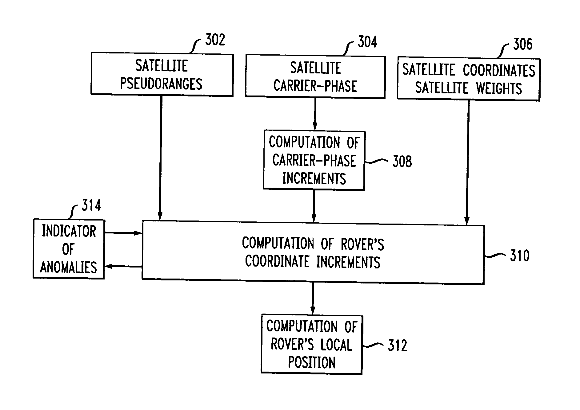
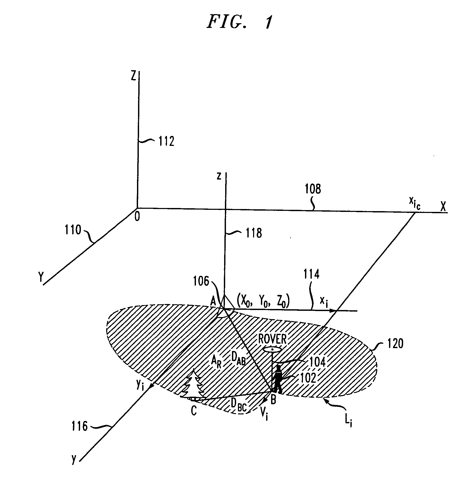
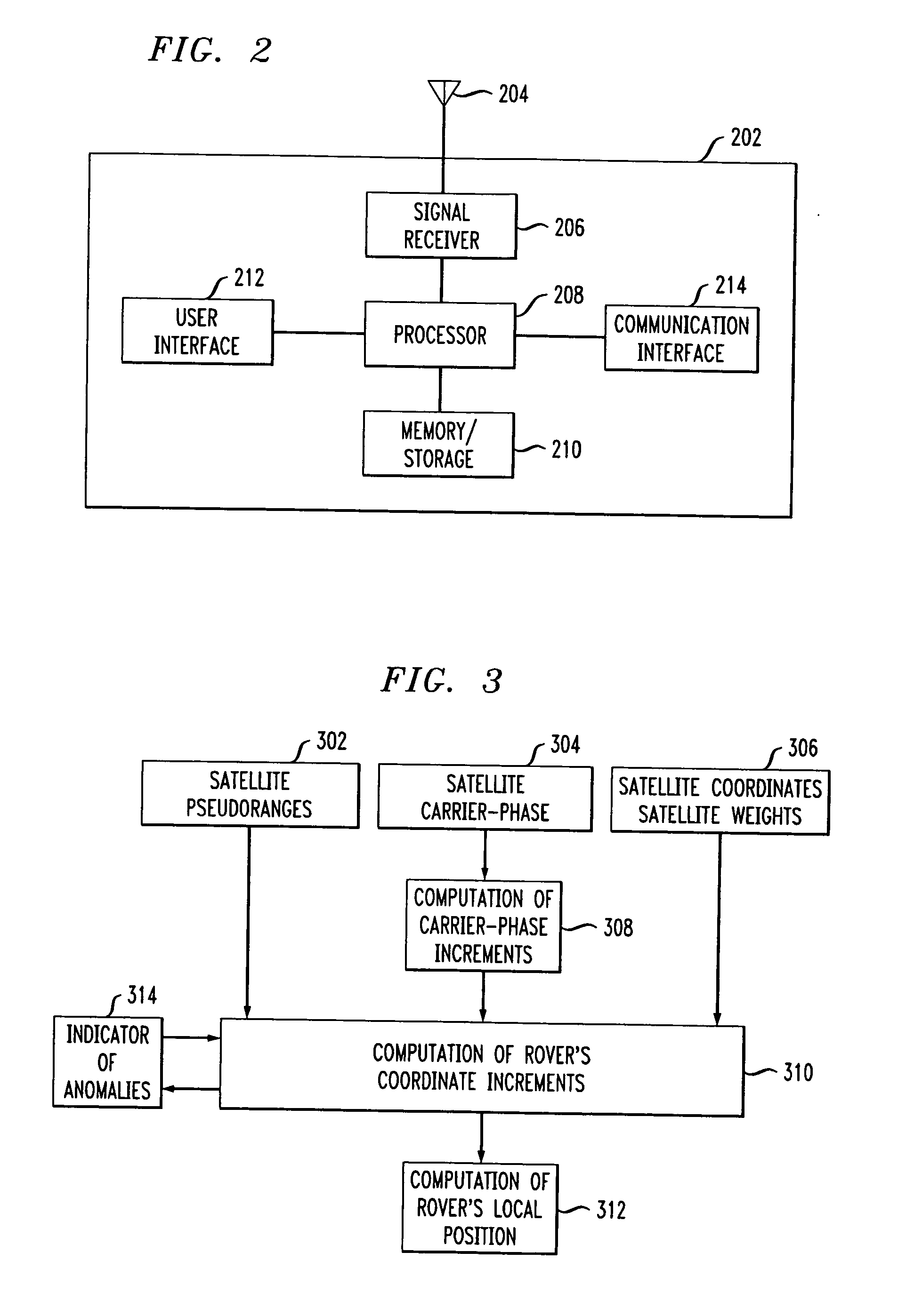
[0022] The present invention is a new technique which provides improved relative position determination accuracy, without the cost and complexity of RTK systems. In accordance with an embodiment of the invention, the relative position of a mobile unit that moves from an initial location to a plurality of successive positions may be determined. The mobile unit receives signals from a plurality of navigation satellites, and tracks the carrier phases of the signals during movement. For each of the received signals, carrier phase increments are calculated over a plurality of epochs. Anomalous carrier phase increments are determined and eliminated from further calculations. The non-eliminated carrier phase increments are then used to calculate coordinate increments for each of the time epochs. If, after elimination, the remaining number of carrier-phase increments is less than a threshold for a particular epoch, then coordinate increments for the particular epoch may be extrapolated using data from prior epochs. In various embodiments, least squares method and Kalman filtering may be used to calculate the coordinate increments. The coordinate increments may then be summed over a plurality of time epochs in order to determine a position of the mobile unit relative to its initial position.

Problems solved by technology

The practical implementation of these advantages, which might otherwise be guaranteed by the measurement of the carrier phases, runs into the problem of ambiguity resolution for phase measurements.
Therefore, the difference in the phase delays of a carrier signal received by the Base and Rover receivers may substantially exceed one cycle.
Second, it is not possible to measure the integer number of cycles from the incoming satellite signals; one can only measure the fractional part.
In most cases the Rover receiver operates in a complicated environment in which various external influences cause measurement errors.
For example, external signals may interfere with the satellite signals, and structures and terrain may result in multipath errors.
Abnormal errors are large systematic errors which may prevent the system from calculating an accurate location.
More often, they are the result of severe exposure of the receiver.
For example, strong reflected signals that interfere with the direct satellite signal would cause an abnormal error.
Similarly, extreme radio interference may also result in abnormal errors.
Partial or complete shading of the Rover receiver may also result in errors due to radio wave diffraction.
If the shading is partial and minor, the measurement error may be minimal.
However, if a satellite is completely shaded (i.e., blocked), all that remains is the multipath signal.
As a result, tracking in the channel is interrupted and the measured phase is lost resulting in an abnormal error.
Dynamic effects on the receiver (i.e., certain motion of the Rover) may also cause abnormal errors.
One specific type of abnormal error is a PLL cycle slip which is a cycle slip in the PLL circuits which are tracking the satellite carrier signal.
When the duration is long enough, tracking is lost.
Normal errors are caused by intrinsic receiver noise and comparatively weak signals reflected from local objects.
In addition, normal errors may result from additional delays in radio waves propagating through the atmosphere, inaccurate knowledge of satellite trajectory, and drift of a satellite's onboard clock.
When considering the use of the above technologies, there is a trade-off between accuracy and cost.
Thus, while providing accurate positioning results, this mode of operation is also the most expensive, in terms of equipment cost, processing power, and complexity.
Alternatively, the least accurate technique is the stand alone system described above, which provides only meter-level accuracy.
While less accurate, this type of system is also the least expensive and least complex, as it requires only a single satellite receiver and no base station.
One stated limitation of this technique is that it can provide accurate positioning measurements over only relatively short time intervals (e.g., 10-30 seconds).

Method used


Image

  • Position determination using carrier phase measurements of satellite signals
  • Position determination using carrier phase measurements of satellite signals
  • Position determination using carrier phase measurements of satellite signals

Examples


first embodiment

[0077] The first embodiment is discussed in conjunction with the flowchart of FIG. 6. The algorithm computes residuals NEVi[j] in step 601 as described above in conjunction with processing block 509 (FIG. 5). In each satellite channel, the magnitudes of residuals (after completion of iterations) are compared to the threshold in step 602. If the threshold is not exceeded by the residual modulo of any channels (as determined in step 604) then the algorithm ends. If the threshold is exceeded by the residual modulo on at least one channel, then in step 606 a search is performed for the satellite channel with the maximum residual. In step 608 the channel weight for the current and following epoch is set to zero for the satellite channel identified in step 606. (In an alternate embodiment, the channel weight for only the current epoch is set to zero if the residual of the satellite channel identified in step 606 is below another defined threshold.) Matrix G is then recomputed in step 610 ...

second embodiment

[0078] The second embodiment is discussed in conjunction with the flowchart of FIG. 7. The algorithm computes residuals NEVi[j] in step 701 as described above in conjunction with processing block 509 (FIG. 5). In step 700, the sum of residuals squares (S NEVi) over all satellite channels is computed. The sum of residuals squares is compared to the threshold in step 702. If the threshold is not exceeded (as determined in step 704) then the algorithm ends. If the threshold is exceeded, then in step706 a search is performed for the satellite channel with the maximum residual. In step 708 the channel weight for the current and following epoch is set to zero for the satellite channel identified in step 706. (In an alternate embodiment, the channel weight for only the current epoch is set to zero if the residual of the satellite channel identified in step 706 is below another defined threshold.) Matrix G is then recomputed in step 710 while eliminating the satellite channel identified in ...


PUM


Abstract

Disclosed is a method and apparatus for determining the relative position of a mobile unit that moves from an initial location to a plurality of successive positions. The mobile unit receives signals from a plurality of navigation satellites and tracks the carrier phases of the signals during movement. For each of the received signals, carrier phase increments are calculated over a plurality of epochs. Anomalous carrier phase increments are determined and eliminated from further calculations. The non-eliminated carrier phase increments are then used to calculate coordinate increments for each of the time epochs. If, after elimination, the remaining number of carrier-phase increments is less than a threshold for a particular epoch, then coordinate increments for the particular epoch may be extrapolated using data from prior epochs. In various embodiments, least squares method and Kalman filtering may be used to calculate the coordinate increments. The coordinate increments may then be summed over a plurality of time epochs in order to determine a position of the mobile unit relative to its initial position.

Description

BACKGROUND OF THE INVENTION [0001] The present invention relates generally to position determination using satellite signals, and more particularly to relative position determination using carrier phase measurements of satellite signals. [0002] Satellite positioning systems, such as GPS (USA) and GLONASS (Russia), are well known in the art and are intended for highly accurate self-positioning of users possessing special navigation receivers. A navigation receiver receives and processes radio signals transmitted by satellites located within line-of-sight distance of the receivers. The satellite signals comprise carrier signals that are modulated by pseudo-random binary codes. The receiver measures the time delay of the received signal relative to a local reference clock or oscillator. These measurements enable the receiver to determine the so-called pseudo-ranges between the receiver and the satellites. The pseudo-ranges are different from the ranges (distances) between the receiver ...

Claims


Application Information

Patent Timeline
Patent Type & Authority Applications(United States)
IPC IPC(8): G01S5/14G01S19/05G01S19/07G01S19/20G01S19/41H04W64/00
CPCG01C21/00G01S19/51G01S19/43
Inventor ZHODZISHSKY, MARK I.VEITSEL, VICTOR A.ZINOVIEV, ALEXEY
Owner TOPCON GPS
Learn More